
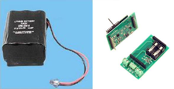
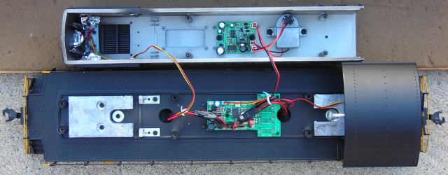
This article details a method of converting a USA Trains S-4 diesel from track power to on board, battery power and radio control using an Aristo-Craft; lithium-ion battery, Plug and Play board, and 2.4 GHz, Revolution Train Engineer receiver.
This small switcher is a challenge to re-power because it has no fuel tank under the frame, limited space under the hood, and no Plug and Play features.
In order to make everything to fit under the hood, the smoke unit and front weight will have to be removed. Anything removed however, will be saved intact to allow the locomotive to be returned to its original condition for re-sale at a later date.
Read the article slowly and completely, making note of the components needed to complete the power conversion.
THE TRACK POWER PICKUPS
It is imperative that the track power pick-ups be disconnected so that the locomotive cannot pick up track power or feed battery power into the tracks. The result could be electronically catastrophic.
Remove the handrails from the sides and ends of the locomotive.
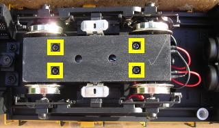
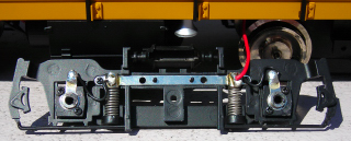
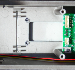
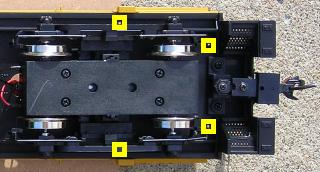
Place the locomotive upside down in a soft cradle taking care not to damage the horn. Remove the four screws outlined in yellow from the bottom of each motor block and remove the bottom covers.
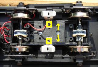
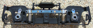
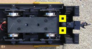
Remove the small screw outlined in yellow from each track slider bracket. Lift out the track sliders and the pieces of piano wire indicated with yellow arrows sprung between the axles.
Clean the sliders and axle wipers. Place them in a Ziploc bag labeled S-4, as well as, the road name and road number.
Fasten the track slider brackets back in place with the small screws. Fasten the covers back on the bottom of each motor block with their four screws.
Do not fully tighten any of the screws until all the screws have been inserted and turned down some. If you tighten the screws as you go, the last few may be hard to insert and may strip the threads in the plastic motor block.
Remove the three screws from each of the side frames, and slide them off the axles.
Unsolder all the wires from the tabs on the axle bushings and the chrome strip above the springs. Place the eight, small wires that ran between the bushings and the chrome strip in the Ziploc bag.
Slide the side frames back on the axles, and fasten each with three screws.
Unplug the two wires from the center of each motor block.
THE HOOD
Remove the six screws outlined in yellow that hold the hood to the frame. They are hidden in deep burrows and will require a long Phillips #1 screwdriver to remove them.
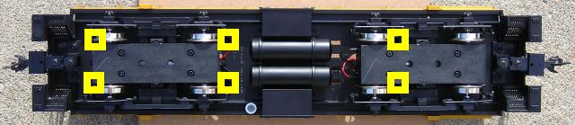
- Two are behind the front pilot just in front of the truck.
- Two are behind the front truck.
- Two are behind the front wheels of the rear truck.
- They can be accessed by placing the screwdriver behind the side frames.
Carefully turn the locomotive over.
Starting from the front of the hood, carefully lift it up until it is just free of the frame and cab.
CAUTION: Do not lift the too far or the wiring connectors may unplug.
Set the hood on the engine cradle beside the frame.
Fasten the six screws back in the hood, so they do not get lost or mixed up with others.
THE TRACK POWER WIRES
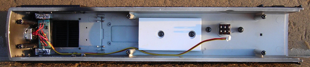
Remove the white twist ties from the wiring. There are four sets of black connectors from the motor blocks under the hood, but only two have four wires on one side of their connectors. These four wires are the track power wires disconnected from each motor block. Unplug the two connectors from the T-shaped, power distribution printed circuit board in the center of the frame, hereafter referred to as the power PCB. Place the track power wires in the Ziploc bag.
THE SMOKE UNIT
In order to make room for the Plug and Play board and receiver, the smoke unit and its PCB will have to be removed.
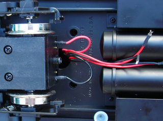
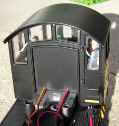
Unplug the two, white plastic connectors, with the red, brown and yellow wires attached, from the power PCB. These wires provide power to the front and rear lights, and will be reconnected later.
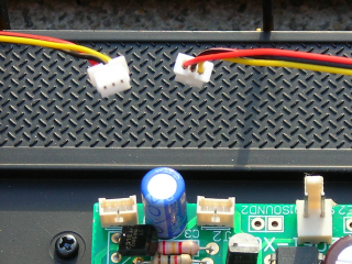
Unplug the white plastic connector, with the red and black wires from the smoke unit PCB mounted inside the top of the hood. These wires provide power to run the smoke unit.
Remove the four screws that hold the smoke unit and its PCB to the hood. Place the PCB and the smoke unit in the Ziploc bag. Fasten the four screws back in the hood so they do not get lost or mixed up with others. They will be used later.
THE PLUG AND PLAY BOARD AND RECEIVER
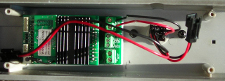
The Plug and Play board and 2.4 GHz Revolution receiver will be mounted on a styrene platform in place of the smoke unit PCB.
Cut to two pieces of 1/8 inch thick styrene, 1 1/2 inches by 2 7/8 inches.
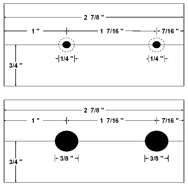
On one piece, lightly score or draw a line a line down the center, 3/4 of an inch from each edge. Mark the line at 1 inch and 2 7/16 of an inch in from the left end. Clamp both pieces of styrene together, and drill a hole through both with a 9/64 inch drill bit at each of the marks.
On one piece, pocket each of the holes 1/32 of an inch with a 1/4 inch Forstner bit. These will fit over the posts left by the smoke unit PCB.
On the other piece, drill the holes out with a 3/8 inch bit. These will pocket the screws so that the Plug and Play board can be mounted flush on the platform.
Glue the two pieces together with the small pockets facing out.
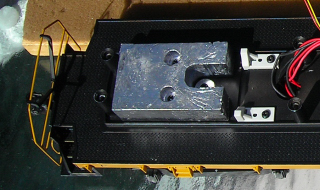
Remove the two screws from the hood and use them to fasten the platform to the hood with the small pockets over the posts.
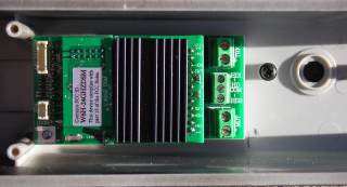
With the screw terminals facing the smoke stack, mount the Plug and Play board, to the platform using the double-sided tape that came with it.
Plug the receiver into the Plug and Play board ensuring all the pins line up properly.
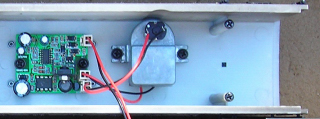
THE BATTERY
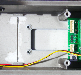
The lithium-ion battery will be installed on a styrene platform in place of the front weight.
Remove the two screws holding the small white brackets to the frame behind the weight. Remove the brackets. Tape the screws to the brackets and place them both in the Ziploc bag with the other parts.
Remove the two screws holding the front weight to the frame. Remove the weight and place it in a separate Ziploc bag to avoid damaging the other parts already removed. Label the bag with S-4, as well as, the road name and road number. Fasten the screws back in the frame so they do not get lost or mixed up with others.
The battery will be mounted on a 1/8 inch thick styrene platform. Cut a piece from the styrene 1 7/8 inches wide by about 4 inches long. Cut a piece 1 7/8 by 2 3/4 inches, and two pieces 1 7/8 by 3/8 of an inch from that piece.
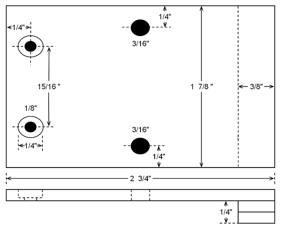
Stack and glue the two small pieces together, flush on all edges. After the glue has dried, sand the edges of the foot until it just fits between the frame rails. Glue the foot flush with the end of the larger piece.
Turn the board over. Lightly score or draw a line 1/4 of an inch from the end opposite the foot. Mark the center point on the line.
On each side of the line, place a mark 15/32 of an inch from the center point. Measure between each of the marks to ensure they are exactly 15/16 of an inch. Adjust if necessary.
Drill a hole at each of the marks with a 1/8 inch bit. Pocket each of the holes with a 1/4 inch Forstner bit until the heads of the screws used to hold the weight are just flush with the surface of the platform.
Lightly score or draw a line across the board at the halfway point. Mark the line 1/4 inch in from each edge. Drill a hole at each mark using a 3/16 inch bit. Feed a long cable tie through the holes as shown.
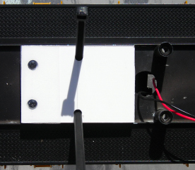
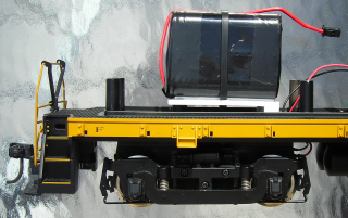
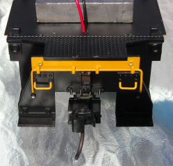
Fasten the board to frame using the two screws that used to hold the weight. Place a piece of hockey shin pad tape or vinyl electric tape across the screw heads as a safety precaution. Fasten the battery to the platform with double-sided tape and secure it with the cable tie. The tie should be snug, but not tight enough to damage the battery.
In the top of the hood there are four pointed brackets. These will interfere with the installation of the hood and could damage the battery. They must be removed.
Twist them off with needle nosed pliers and smooth the area with a Dremel tool.
The square brackets on each side of the hood can remain.
THE BATTERY SWITCH
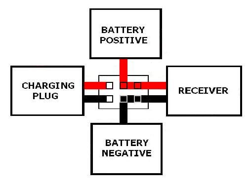
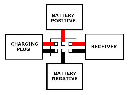
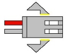
As the battery will be charged on-board, a double-pole double-throw (DPDT) switch is needed to toggle the battery between its charging connector and the receiver. The switch will be installed so it toggles forward and backward.
Toggling the switch backward will connect the battery through one end of the switch to its charging connector.
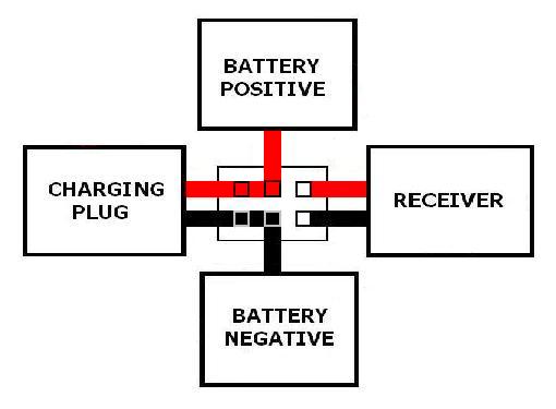
Toggling the switch forward will connect the battery through the other end of the switch to the receiver to power the locomotive.
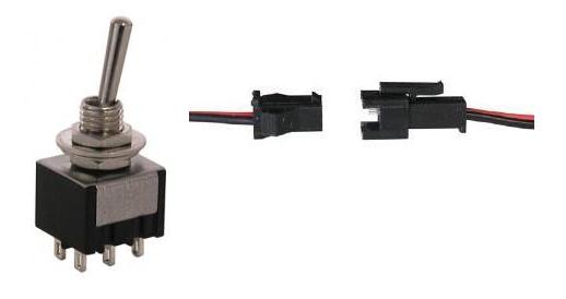
The DPDT center-off switch and 2-pin connector sets used to connect it are both available from All Electronics under catalog numbers MTS-12 and CON-240 respectively. OVGRS members can purchase the DPDT switch and connector sets by contacting Paul Norton.
The switch will be installed under the smoke stack which was designed to pop on and off to fill the smoke unit. This will allow the switch to be easily accessible, but hidden when running the locomotive. To make adding the wiring easier, it will be soldered and shrink wrapped to the switch before the switch is installed.
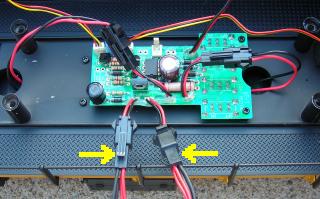
THE BATTERY CONNECTOR
The male half of an All Electronics, 2-pin connector set is used to connect the lithium-ion battery to the DPDT switch. It has the same connector as the Aristo-Craft, lithium-ion battery charger.
CAUTION: The wires on the connector sets sold by All Electronics may not be positioned the same as the wires on the connectors of lithium-ion batteries and chargers. If not, click on the following link to see how to switch the positions of the AE Connector Set Wiring so that proper polarity is maintained.
Cut the wires of the male half of an AE connector set to a length that will easily reach from the exhaust stack to the connector on the lithium-ion battery. Solder and shrink wrap the wires to the center terminals of the switch as shown in the following diagram.
CAUTION: Do not connect the lithium-ion battery at this time.
THE BATTERY CHARGING CONNECTOR
The battery charging connector will be mounted on the rear pilot just under the coupler lift bar. Remove the grab irons from the rear of the cab.
Flip the locomotive over and remove the four screws outlined in yellow holding the cab to the frame. Remove the cab and fasten the screws back in it so they do not get lost or mixed up with others. Set the cab aside for now.
Remove the two screws holding the coupler bracket to the frame. Remove the bracket and coupler, and set them aside for now. Fasten the screws back in the frame so they do not get lost or mixed up with others.
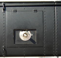
The female half of the AE connector set will be used as the battery charging connector. It has the same connector as an Aristo-Craft, lithium-ion battery. Trim the wings off the connector and sand the sides of it smooth.
Drill a hole with a 1/8 inch bit in the rear pilot just under the center of the coupler lift bar. With the notch on the connector facing up, feed the wires through the hole until the connector is snug against the pilot.
Drill a hole with a 1/8 inch bit in the center of the frame, about 1/4 of an inch from the back of the rear weight. Feed the connector wires through the hole until they are snug.
Remove the screws from the bottom of the frame and fasten the coupler bracket and coupler back on.
Drill a hole in the bottom of the front wall of the cab, opposite the rear light wiring, using a 1/8 inch bit. Feed the connector wires through the hole until they are snug.
Extra lengths of wire can be soldered and shrink wrapped to the end of the connector wires so they can be soldered and shrink wrapped to the switch as shown in the following diagram. If you want to be able to remove the cab easily however, you may want to use another connector set between the ends of the wires and the switch.
Re-install the cab and grab irons. Re-connect the rear lights to the power distribution PCB.
WIRING THE RECEIVER
The receiver will have to be connected to the DPDT switch so it can be powered by the battery, and connected to the power PCB so it can power the motors and lights. The motors, lights, and switches on the bottom of the locomotive will behave as they did under track power.
Cut a length of red and a length of black wire that will easily reach from the exhaust stack to the screw terminals on the Plug and Play Board. Solder and shrink wrap the wires to the switch as shown in the following diagram.
Remove the exhaust stack and install the switch so it toggles forward and backward. A nut and the star washer are on the inside of the hood; the tab washer and second nut are on the outside. The wires for the charging connector face the front of the hood, the wires for the receiver toward the rear.
If you want the exhaust stack to fit completely flush, trim and file the edge of the tab washer as shown.
Trim about 3/16 of an inch of insulation off the other end of the red and black wires soldered to the DPDT for the receiver, and tin them with solder. Install the ends of the wires in the two power input screw terminals on the Plug and Play board marked “TRK”.
The male half of an EA connector will be used to connect the receiver to the power PCB. It has the same connector as an Aristo-Craft, lithium-ion battery charger.
Trim about 3/16 of an inch of insulation off the ends of the wires of the connector, and tin them with solder. Install the ends of the wires in the two power output screw terminals on the Plug and Play board marked “MOT”.
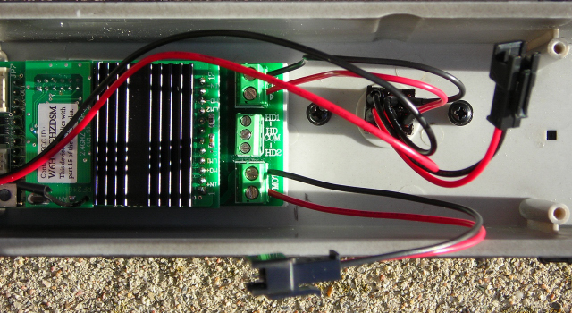
Connect the AE connector to the connector on the power distribution labeled “Power – 1”. Check to ensure the colour coding of the wires on both connectors match.
THE LINKING SWITCH
If you wish to install the remote linking switch, a 5/16 inch hole will have to be drilled in the locomotive in a hidden but accessible spot. On my switcher, I replaced the momentary switch with a small reed switch and fastened it to the inside of the hood with hot glue.
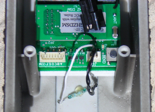
A dollar store telescoping magnet will activate the switch and linking process by touching the top of the hood above the switch.
ACTIVATING THE BATTERY
CAUTION: Check to ensure all the wiring on one side of the DPDT switch is red, and all the wiring on the other side is black. Check that the DPDT switch is in the center-off position. Check to ensure the colour coding of the wires on the lithium-ion battery and the connector soldered to the center terminals of the DPDT switch match. Plug in the battery.
CHARGING THE BATTERY
If the battery has not been charged, connect an Aristo-Craft, lithium-ion battery charger to the connector on the rear pilot and toggle the DPDT rearward. The charger should be removed when the battery reaches 25.2 which should require less than four hours. Return the switch to its center-off position and remove the charger.
PROGRAMMING THE RECEIVER
To power the receiver, toggle the DPDT switch forward.
To program the receiver follow the instructions in the Installation and Operation Manual for the Revolution Train Engineer on the CD that came with the set. The Revised Manual and other information is also available on the Aristo-Craft web site as an Adobe pdf file. To read or download the revised manual, click on the link.
Test the locomotive to ensure it responds to the transmitter.
After testing has been successfully completed, re-connect the front lights to the power PCB and fasten the shell to frame. Be careful not to pinch any of the wiring between the shell and the frame rails.
CONGRATULATIONS! You have successfully converted an USA Trains S-4 switcher to on-board, battery power and radio control.
7 comments
Skip to comment form
Paul,
Have you converted the lights in the USAT S-4 to LED? If so, what LED bulbs did you use?
Thanks!
As I remember the S4 has LED lights. So there was no reason to make my own LED circuit boards as I have for other USA Trains diesels.
Paul,
Does it matter which plug (Power 1 or Power 2) on the Power PCB I connect the REVO TRK connector to? THX
I meant to say “Does it matter which plug (Power 1 or Power 2) on the Power PCB I connect the REVO MOTOR connector to?”
Hi Joe!
It does not matter, as both power are connected by traces on the USAT Printed Circuit Board.
Sorry for the delay Jerry. I bought a new computer and spent the last week learning how to use Windows 8 and get the printers to work for both my machine and Penny’s laptop. What a PITB this new operating system is.
The information you need is in the article on adding MU connectors to the SD-70.
https://ovgrs.ca/the-trains/mu-connectors/usa-trains-sd70-mac/
Was wondering why the battery conversion for USA Mac 70’s was removed need to see, or diagram of installation of mu plugs in engine and screw placement to take shell off?????? Thanks