
This project shows how to add an MU connector to the rear of an LGB Mallet so a trailing car can be used to battery power and radio control the locomotive.
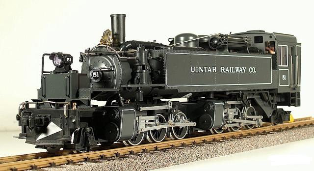
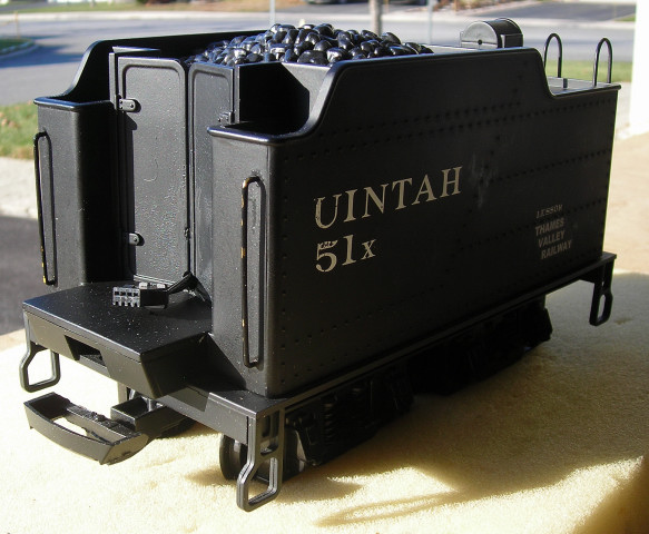
The most suitable trailing power car for this locomotive is an LGB American Tender. For this project it was equipped with an Aristo-Craft lithium-ion battery pack and a Revolution receiver. To see how it was assembled, just click on the link.
When the Mallet was tested with this power car the motors and sound board functioned well, however the headlight did not light until top speed. It is assumed that, like most USA Trains diesels, the voltage regulator that powers the front headlight is incompatible with the Pulse Width Control (PWC) output of the Revolution receiver. There were two possible ways to correct this problem.
The first and simplest way would be to install an Aristo-Craft, PWC to Linear Board (CRE-57091) in the power car between the motor wires of the Revolution receiver and the wires of the MU connector. The motors, headlight, and sound would perform exactly as they did with track power. Unfortunately we did not have the required board.
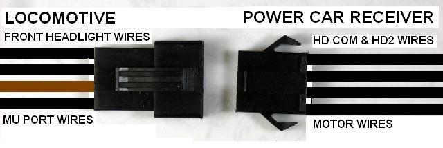
The second method involves opening the Mallet, unplugging the front headlight wires, and extending them to the back of the locomotive. The headlight and MU port wires are then attached to a connector on the back of the locomotive that plugs into the connector on the power car.
The article appears long because it detailed and includes a lot of pictures. But if you take your time and follow it step-by-step it is not difficult, and the results are well worthwhile.
Please read this article carefully, highlighting the components that are needed. Sources of supply are suggested for items not sold by hobby suppliers. OVGRS members can purchase the required components by contacting Paul Norton.
Nothing in this project prevents a Mallet from being restored to track power for re-sale at a later date.
OPENING THE LOCOMOTIVE
During the project several different sizes of screws will be removed and placed in a small container. To ensure the correct sized screw is refastened in the proper place during the reassembly of the Mallet, the screws will referenced by the page and part number in the Service Manual for the locomotive. The Mallet Service Manual can be downloaded by clicking on the link.
If you have other LGB equipment, other Service Manuals can be downloaded from the Model Train Forum by clicking on this link.
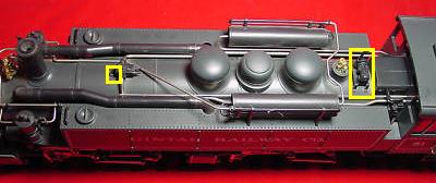
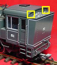
Remove the steam generator, outlined in yellow in front of the cab, from the top of the boiler to prevent it from getting damaged. It is a press fit. Place it in a small Ziploc bag and set it aside for now.
In order to open the locomotive 10 screws need to be removed: 4 heavier screws part 20882-162, and 6 lighter screws part 20882-163.
Remove the heavier screw (page 2, part 20882-162) outlined in yellow from the top of the boiler behind the smokestack, and place it in a small container.
Carefully place the locomotive upside-down on a soft, engine work cradle.
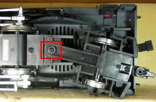
The trailing truck will be removed to make it easier to remove the screws under the cab, and make the locomotive less awkward to handle. Remove the heavier screw and washer (page 7, parts 20882-162 and 20882-169) outline in red from the front of the trailing truck. Remove the trailing truck and place it in the small Ziploc bag with the steam generator. Fasten the heavier screw and washer back in the sub frame of the rear power truck, so they do not get lost or mixed up with others.
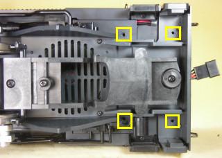
Remove the four lighter screws (page 3, part 20882-163) outlined in yellow from the bottom of the frame under the cab. Place them in the small container with the other screw.
Remove the two heavier screws (page 3, part 20882-162) outlined in red from the bottom of the frame. They are inside the front of the fire box walls. Each can be reached by pivoting the rear power truck completely to the opposite side. Place them in the small container with the other screws.
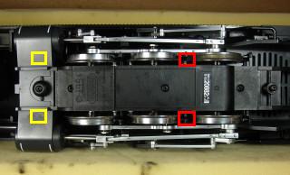
Remove the two lighter screws (page 3, part 20882-163) outlined in yellow from the boiler. They are below the steam chest of the rear power truck, and are hidden behind the cylindrical steam lines hanging next to the sides of the boiler. Each can be reached by pivoting the power truck completely to the opposite side. Place them in the small container with the other screws.
Carefully set the locomotive on its wheels beside the engine work cradle. Gently lift the top of the locomotive off its frame, and place it on the work cradle.
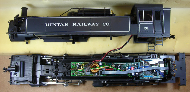
That completes the opening of the locomotive.
FRONT HEADLIGHT WIRES
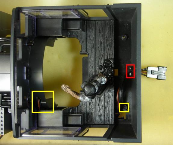
The front headlight wires are fastened to posts outlined in red and labeled Lampe on the front of the main circuit board. Slide the slip-on metal terminals up off their posts.
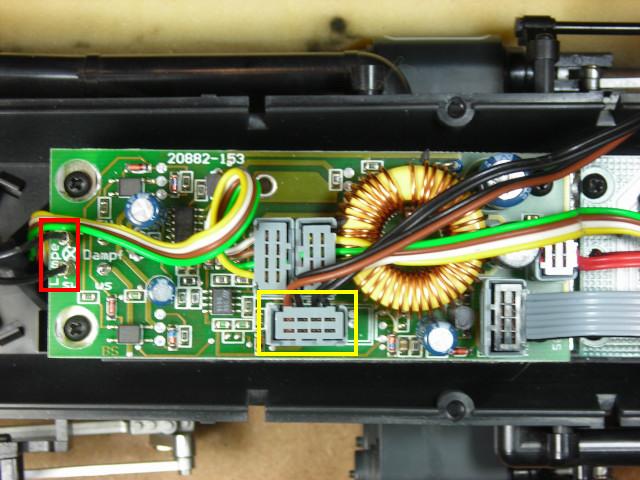
During this project the smoke unit and cab light bulb were removed from the locomotive to extend battery run times. The slip-on metal terminals for the smoke unit were on posts labeled Dampf right behind the posts for the front headlight.
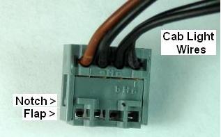
As the cab light is not used, its wires were used to extend the headlight wires. The gray connector outlined in yellow contains the two black cab light wires. Lift the connector off its four pins. Lift the bottom of the flaps on the sides of the connector up slightly to clear the notch under each. While holding the flaps free of the notches, pull the top and bottom parts of the connector apart with your third and fourth hands. 😉 OK, maybe a small piece of tape stuck to the underside of the flaps would work. I guess the engineer that designed this device never envisioned someone taking it apart to repair or remove a wire. End rant.
The cab light wires are held in the top of the connector with small, fragile copper terminals. Carefully pull the two on the right down out of the top of the connector. Pull the cab light wires out of the connector. Slide the copper terminals back in place. Close the connector ensuring that both flaps engage the small notches on the sides. Push the connector back in place over its four pins so the remaining brown and black MU wires will be powered.
Do not remove the metal terminals from the headlight wires, as you may want to restore the locomotive to its original condition at a later date. Place a length of shrink wrap over and past each of the terminals. The wires may have to be separated a bit more so the shrink wrap is past the metal terminals when they are being soldered. Remove the small bits of insulation off the ends of the cab light wires. Solder and shrink wrap the wires to the metal terminals on the headlight wires as shown in the following picture.
MU CONNECTOR
Remove the four shorter screws (page 3, part 20882-161) from under the corners of the cab roof. Lift the roof off and set it aside for now. Place the four screws in the small container with the rest of the screws.
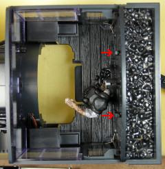
Under the cab is a tab locking the rear wall of the cab to the floor. While holding the doors inward with one hand so the tops do not catch on the cab, push the tab forward and up. The tab should release and the rear wall rise slightly. While still holding the doors inward, grasp the top of the rear wall and lift it upwards about 3/4 of an inch.
The coal load is attached to the rear wall of the cab with two tabs indicated with the red arrows. Grasp the coal load at the ends and pull the back up and push the front down and away from the wall to remove the tabs from their slots. The bottom of the coal load must clear small notches in the rear wall that hold it up in place. Set the coal load aside for now.
Remove the cab light bulb from its socket and place it in a small Ziploc bag. Using a small, flat screwdriver push the light bulb socket forward out of its plastic sleeve. Unsolder it from it wires, and place it the small Ziploc bag with the bulb. Push or pull the wires through the hole in the rear wall. Holding the doors inward, remove the rear wall from the cab.
Unsolder the wires for the MU sockets from the tabs outlined in red on the back wall of the coal bunker. Move the wires away from the back of the coal bunker.
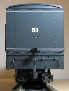
Using a 5/32nd inch bit, drill a hole in the back of the coal bunker between the grab irons. The hole should be above the rivets and just below the pin striping.
If you have a D-sub crimper, pass all four wires through the hole drilled in the back of the coal bunker and crimp a male terminal on each. The male terminals are available from coolight.com. OVGRS members can purchase the terminals by contacting Paul Norton.
If there is not enough slack in the MU and headlight wires, remove the wires from the slot in the left hand side of the boiler and work them down through the channel in the bottom of the cab. The slot in the boiler is outlined in the yellow in the previous picture of the cab interior.
With the locking tab of a four-wire male connector facing up, plug the wires into back of the connector in the order shown in the following diagram.
If you do not have a D-sub crimper, pass the wires of a four-wire male connector back through the hole in the back of the coal bunker. Solder and shrink wrap the MU and headlight wires to the four wires of the connector using the diagram above as a guide.
If there is not enough slack in the MU and headlight wires, remove the wires from the slot in the left hand side of the boiler and work them down through the channel in the bottom of the cab. The slot in the boiler is outlined in the yellow in the previous picture of the cab interior.
The 4-wire connector sets are available from All Electronics under catalog # CON-440. OVGRS members can purchase these connector sets by contacting Paul Norton.
That completes the installation of the MU connector.
RE-ASSEMBLING THE MALLET
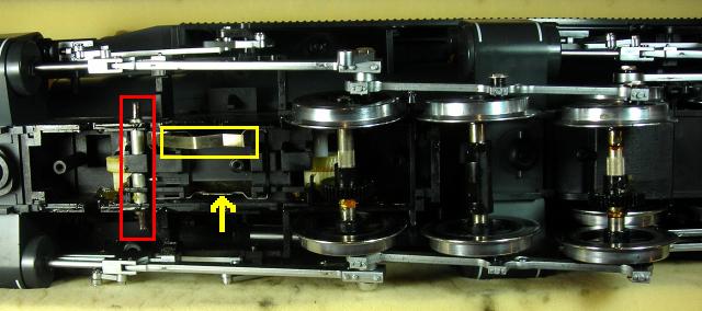
Remove any unnecessary slack in the wires, and re-route them through the slot in the boiler if necessary. Ensure the wires in the bottom of the coal bunker pass around behind the screw post outlined in yellow in the following picture, so they do not interfere with the installation of the rear cab wall. Please don’t ask me how I know.
Slip the tabs on the coal load back into the slots on the rear cab wall and snap it up in place. While holding the doors inward, slide the wall down the slots in the sides of the cab until the tab on the bottom locks the wall to the floor.
Use the four shortest screws (page 3, part 20882-161) in the small container to install the roof.
Remove the top of the steam dome closest to the cab. Remove the disc from around the blue sound volume shaft inside the dome. Place the top of the locomotive back on the frame, using the rear ladders and sound volume shaft as a guide. The boiler halves should fit together easily without gaps. If they do not, lift the boiler and check for wires in the way of the post at the front and other areas.
Carefully place the locomotive upside-down on a soft, engine work cradle, taking care not to dislodge the boiler.
Install four of the lighter screws (page 3, part 20882-163) in the holes outlined in yellow in the bottom of the frame under the cab.
Install two of the heavier screws (page 3, part 20882-162) in the holes outlined in red in the bottom of the frame. They are inside the front of the fire box walls. Each can be reached by pivoting the rear power truck completely to the opposite side.
Fasten the two remaining lighter screws (page 3, part 20882-163) in the holes outlined in yellow in the bottom of the boiler. They are below the steam chest of the rear power truck, and are hidden behind the cylindrical steam lines hanging next to the sides of the boiler. Each can be reached by pivoting the power truck completely to the opposite side.
Remove the heavier screw and washer (page 7, parts 20882-162 and 20882-169) outline in red from the bottom of the rear power truck sub frame. Use them to install the trailing truck.
Carefully set the locomotive on its wheels beside the engine work cradle.
Fasten the remaining heavier screw (page 2, part 20882-162) in the hole outlined in yellow in the top of the boiler behind the smokestack. Do not install the steam generator at this time.
REMOVING THE TRACK POWER PICK-UPS
It is imperative that the track power pick-ups be removed to ensure the locomotive cannot pick up track power or feed battery power into the tracks. The result could be electronically catastrophic.
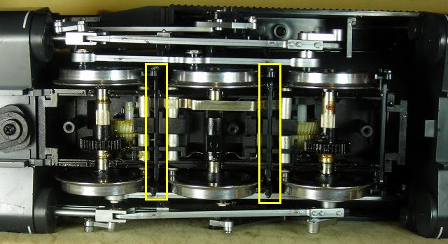
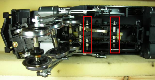
Carefully place the locomotive upside-down on a soft, engine work cradle. Remove the four bolts (pages 4 and 6, part 20882-165) outlined in red from the reversing linkage of the power trucks, and place them in a small container.
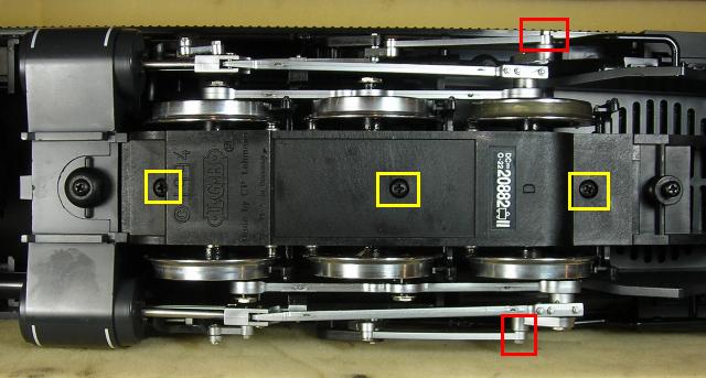
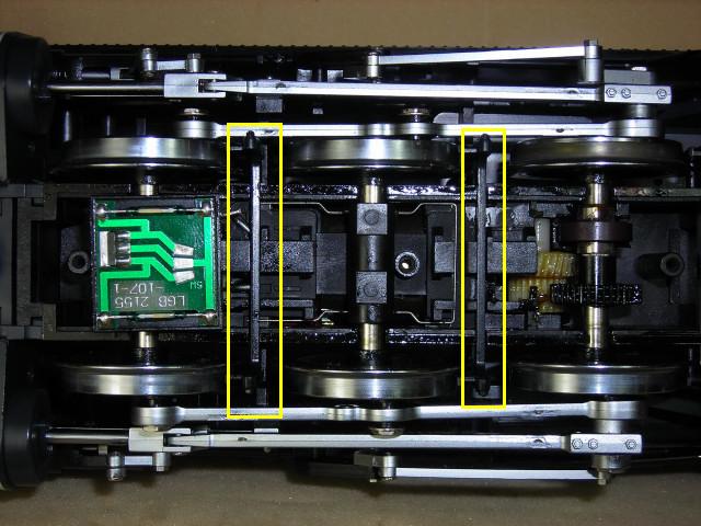
Remove the six screws (page 5 and 7, part 20882-167) outlined in yellow from the bottom covers of the power trucks, and place them in the small container. Remove the bottom covers, and set them aside for now.
Each power truck has a pair of brake shoe holders; the bottoms of which are shown outlined in yellow. Slide a small flat screwdriver down between the wheels and gently lift the pins on the top of each side of the holders out of the power truck cases. Lift the holders up and out, and set all four aside with the bottom covers of the power trucks.
Lift the rear wheels and axles of both power trucks to access the carbon brushes outlined in red. Remove the eight sets of carbon brushes and their holders for the rear wheels. Place them in the small Ziploc bag with the cab light bulb and socket.
Lift the front axle and wheels back in each power truck. Remove the two (only one shown) wide axle wipers outlined in yellow from each of the power trucks, and place them in the Ziploc bag. DO NOT LIFT the thin center axle spring indicated with the yellow arrow from each power truck.
The power trucks should look this empty when all the track power pick-ups are removed. Apply a little LGB grease to the gears.
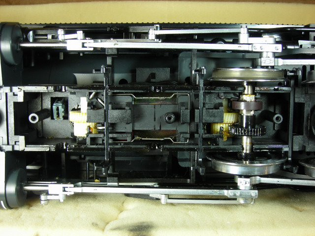
Place the wheels and axles back in place ensuring that the gears are properly meshing. There should be a slight bit of slack in each wheel set. The slots in the black plastic collars on the center axle should be resting on the spring. Slide the brake shoe holders back in place between the wheels of each power truck. The pins on them should snap back into the power truck cases.
Place the cover back on the bottom of each power truck. Install the six screws (page 5 and 7, part 20882-167) outlined in yellow in the bottom covers.
Fasten the four bolts (pages 4 and 6, part 20882-165) outlined in red back in the reversing linkage of the power trucks.
Carefully turn the locomotive back over onto its wheels. Mount the steam generator back on top of the boiler in front of the cab.
Label the Ziploc bag containing the parts that have been removed with locomotive type (Mallet), as well as, its road name and number. Place the bag in the locomotives packaging so it does not get lost.
CONGRATULATIONS! You have successfully installed an MU connector on your LGB Mallet.
By connecting a power and control car to it, you will be able to enjoy the benefits of battery power and radio control.
1 comment
I just purchased the Mallet in Arizona and am attempting to convert to battery power. Co-incidentally I belong to the OVGRS in Ottawa as that is where my summer home is located. I was surprised to find this article on conversion. Thanks.