
27 August 2020
Be aware that some of the USA Trains locomotive project articles that I posted years ago are somewhat out of date. The Crest Revolution receivers at that time all had Pulse Width Control for the output power. The voltage spikes in PWC would not let the light bulbs work properly in some USAT diesels. As I result I removed the USAT main circuit board and headlight circuit boards and replaced the headlight and number board lights with LEDs.
Precision RC now makes DC Linear Revolution receivers, so you no longer have to remove the main circuit board and change the lights in USAT diesels. Some of the new USAT diesels also have LED lights that work with the Revolution PWC receivers.
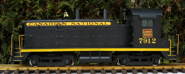
This article details a method used to convert a USA Trains NW-2 diesel switcher from track power to on-board, battery power and radio control using an Aristo-Craft lithium-ion battery and a Revolution receiver in a Plug and Play Board.
As the voltage regulator used by USA Trains to power the headlights is incompatible with the Pulse Width Control (PWC) output of the Revolution receiver, the motor wires of the receiver cannot be used to power both the motors and the lights through the locomotive’s main circuit board. This could be rectified by adding an Aristo-Craft, PWC to Linear DC Board (CRE 57091) to the motor wires, as it converts the output from PWC to linear DC. However my efforts to do so have revealed that it is easier and less expensive to connect the two headlights directly to the lighting output terminals (HD1, HD COM, HD2) on the Plug and Play Board.
As the battery switch and receiver will control all the functions of the battery, charging connector, motors, and lights; the USA Trains electronics are redundant and can be removed. The redundant factory electronics will be stored intact in a large Ziploc bag, so nothing prevents the locomotive from being restored to its original condition for re-sale at a later date.
Please read this article carefully, noting the components that are needed. Sources of supply are suggested for items not sold by your hobby suppliers. OVGRS members can purchase the electronic components by contacting Paul Norton.
The article may appear long because it detailed and includes a lot of pictures. But if you take your time and follow it step-by-step it is not difficult, and the results are be well worthwhile.
OPENING THE LOCOMOTIVE
Remove all the handrails from both ends of the locomotive so they do not get bent or the stanchion bases broken. Place them in a small Ziploc bag, and set them aside for now. They will be re-installed when the locomotive is re-assembled.
Place the locomotive flat on its side on a soft surface. Placing it upside-down would damage the horn and bell.
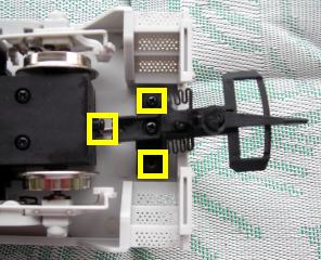
Undo the screw that holds each of the brackets for the coupler centering springs to the frame. It is just under the motor block at each end of the frame. Undo the two screws that hold each of the coupler brackets to the frame. Place the coupler brackets, couplers, return springs, and small metal brackets in a small Ziploc bag; and set them aside for now. They will be re-installed when the locomotive is re-assembled. Fasten the screws back in the frame so they do not get lost or mixed up with others.
Remove the three screws from each of the upward facing sideframes, and place them in a small container. Slide the sideframes off the wheel axles. Clean the black grease off the sideframe bushings and wheel axles.
Turn the locomotive over. Remove the screws and sideframes. Place the screws in the small container. Clean the black grease off the sideframe bushings and the motor block wheel axels.
Unplug the four wires from each of the motor blocks. Set the motor blocks aside for now, they will be re-installed when the locomotive is re-assembled.
It is imperative that the track power wiring be removed to ensure the locomotive cannot pick up track power or feed battery power into the tracks. The result could be electronically catastrophic. Unsolder all the three wires from the tabs on the inside of all the sideframes.
Place the sideframes in a small Ziploc bag and set them aside for now. They will be re-installed when the locomotive is re-assembled. Fasten all the sideframe screws back in the motor block cradles so they do not get lost or mixed up with others.
Place the small black wires in a large Ziploc bag labeled NW-2 along with the road name and number. This bag will be used to store all the electronics removed from the locomotive.
Wash the black axle grease off your hands so it does not stain the locomotive paint or your clothing.
Undo the four screws that hold the fuel tank to the frame.
Remove the fuel tank, and set it aside. It will be re-installed when the locomotive is re-assembled. Fasten the four screws back in frame so they do not get lost or mixed up with others.
There are 8 screws in the bottom of the frame that hold the cab and hood to the frame.
Remove the 8 screws and place them in the small container. Turn the locomotive right side up. Holding the back of the cab, carefully lift forward and up. The cab and hood will lift off as one piece. Do not lift it up too far or the wiring connectors may unplug. Set the cab and hood beside the frame.
Fasten the 8 screws back in the cab and hood so they do not get lost or mixed up with others.
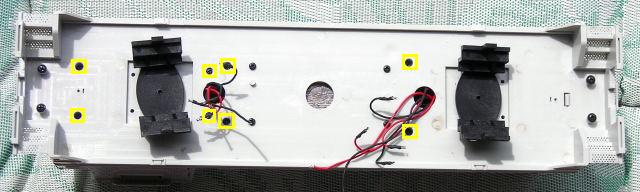
Remove the two, white twist ties from the wiring, and place them in the large Ziploc bag.
Undo the 2 screws and remove the voltage regulator and heat sink from the weight in the center of the frame. Tape the 2 screws in the holes of the heat sink, and place the heat sink in the large Ziploc bag.
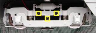
Unplug the 4-wire, white plastic connector from the small printed circuit board (PCB) in front of the weight.
Set the cab and hood aside for now.
REMOVING THE ELECTRONICS FROM THE FRAME
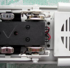
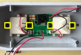
Undo the two larger screws that hold the weight to the center of the frame. Remove the screws, washers, and weight and set them to one side.
Draw the motor block wires through the holes in the frame. Undo the 3 small screws that hold the two Printed Circuit Boards (PCBs) to the frame. Remove the two PCBs and the wiring and place it in the large Ziploc bag. Fasten the three small screws back in the frame so they do not get lost or mixed up with others.
Fasten the weight back to the center of the frame with its two screws and washers.
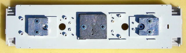
That completes the removal of the factory electronics from the frame.
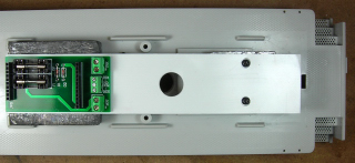
THE COMPONENTS PLATFORM
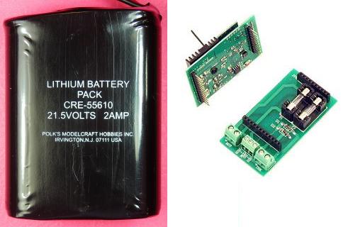
A styrene platform will be made to hold the Aristo-Craft: lithium-ion battery, Plug and Play Board, and Revolution receiver.
Score and snap two strips of 1/16th inch thick styrene, 1 5/8 inches wide by 7 1/4 inches long.
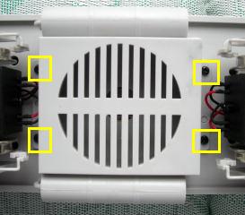
Remove the four screws and washers from the center and front weights, and place them in a small container.
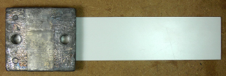
Place one of the strips across the two weights; one end should be flush with the back of the center weight, and the edges of the other end flush with the edges of the front weight. Score lines across the center weight flush with both edges of the strip.
Remove the center weight, and securely tape one of the styrene strips to the top of it. The end of the strip should be flush with the back of the weight, and edges centered between the two scored lines. Hockey shin pad tape is great for this as it stretches somewhat, sticks well, and will not leave glue behind.
Place the center weight back on the frame to ensure the styrene is still flush with the edges of the front weight.
Lift the center weight and styrene strip off, and turn them over. Insert a 5/16ths inch drill bit in each of the holes in the weight, and turn the drill bit with your fingers to make a circular mark in the styrene sheet.
Remove the tape and the styrene strip from the weight. Place the center weight back on its mounting posts.
Tape both pieces of styrene together ensuring the edges and ends are flush, and the marks made with the drill bit are facing out. Using the marks as a guide, drill two holes through both pieces with a 1/8 inch bit.
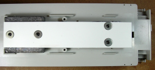
Fasten both strips to the center weight using two of the screws in the small container. The edges of the strips should align with the sides of the front weight.
Turn the frame over. Insert a 3/32nd inch drill bit in each in of the holes in the top of the posts for the front weight. Twist the drill bit with your fingers to place a mark in the styrene sheet.
Turn the frame back over and unfasten the strips from the center weight. Place the screws in the small container.
Using the new marks as a guide, drill two holes through both pieces with a 1/8 inch bit. Test fit the strips to the weights using the four screws in the small container.
Unfasten the strips from the weights, and place the screws in the small container. Place a pencil mark across one edge of both strips. Remove the tape from the strips.
Enlarge the holes in the top strip only using a 1/4 inch drill bit.
Using the pencil marks as a guide, glue the two strips together ensuring the edges and ends are flush, and the holes are properly aligned. I tried several glues and found that Testors plastic cement was the easiest to use and held the pieces together well. Use the screws and washers in the small container to fasten the strips to the weights until the glue cures.
When the glue has cured, undo the four screws and remove the styrene platform from the weights. Place the screws and washers in the small container
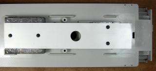
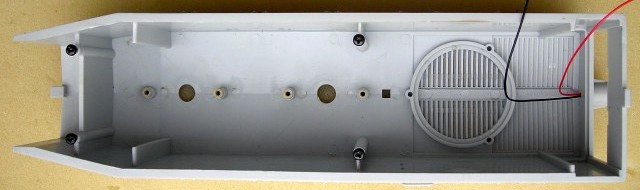
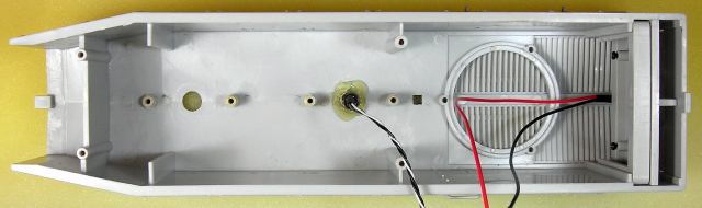
Draw a line across the platform 3 inches from the front end. Measure to the center point of the line and place a mark. Drill a hole using a 5/8ths inch spade bit at the mark. Smooth any sharp edges around the hole with fine sandpaper. This hole will be used to feed wires to the Plug and Play Board for the receiver.
Fasten the platform back on the weights with the four screws in the small container. If the front holes are slightly off, enlarge them with a 9/64ths inch drill bit. Place the washers in the large Ziploc bag with the rest of the electrical components. That completes the assembly and installation of the components platform.
THE PLUG AND PLAY BOARD
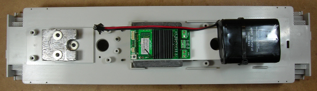
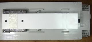
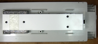
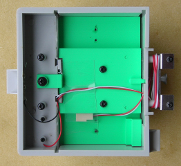
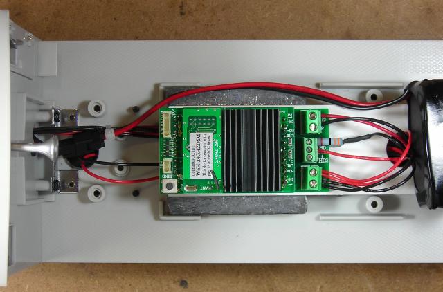
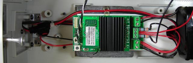
Fasten the Plug and Play Board on the rear of the components platform as shown with the double-sided tape provided. The end of the board should be flush with the end of the platform. The screw terminals should face the front weight.
Plug the Revolution receiver into the Plug and Play Board and raise the antenna.
That completes the installation of the Plug and Play Board and Revolution receiver. They will be wired as the battery switch, motors, and lights are installed.
THE LITHIUM-ION BATTERY
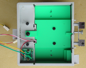
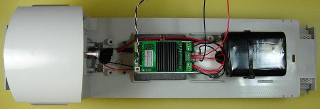
Fasten a strip of double-sided tape across the heads of the screws in the front of the platform. Fasten another strip across the platform in front of the hole for the motor wires. Use the tape to fasten the lithium-ion battery to the front of the platform as shown. The bottom of the battery should be flush with the end of the platform.
Test fit the hood to the frame. Adjust the position of the battery if necessary.
Remove the hood and set it aside for now. Fasten a cable tie around platform and across the top of the battery. The cable tie should up against the back of the weight. The tie should be snug but not tight. Trim the excess from the cable tie.
That completes the installation of the battery. It will be connected when the battery switch is installed.
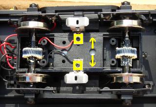
MOTOR BLOCKS
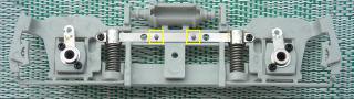
The motor blocks will be opened to remove the track power sliders, inspect and lubricate the gears, and rewire the motors. Turn the motor blocks over and remove the four screws and bottom cover from each of them.
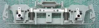
Remove the small screws from the chrome brackets in the motor blocks, and place them in the small container. Lift the chrome brackets, and remove the track power sliders and wire wipers sprung between the axles. Wipe the grease off them, and place them in the large Ziploc bag. Fasten the chrome brackets back in place with the small screws.
Lift the axle sets out. If you can gently turn a wheel while holding the other, the axle sleeve on the drive gear is split. They can be fixed using the method in the DRIVE GEAR AXLE SLEEVES repair tip, or replaced with complete axle assemblies. If you wish to get rid of rubber traction tires, order axle assemblies without them from USA Trains.
If necessary, lubricate the axle drive gears with plastic compatible grease. Place the axle assemblies back in the motor blocks. Ensure their bushings are seated flat in the slots in the sides of the motors blocks. Pop the covers back on and fasten them with their screws. Do not fully tighten any of the screws until all the screws have been inserted and turned down some. If you fully tighten the screws as you go, the last few may be hard to insert and may strip the threads in the plastic motor block.
The small and sometimes unreliable slip-on connectors that plug into the front of the motor blocks will be replaced with wires soldered directly to the motor terminals. Remove the four screws and the top cover from each of the motor blocks. Place the screws in a small container so they do not get lost.
Lift the motors out of the blocks. Remove the small, lash adjusting assemblies from the ends of the motor shafts and place them in the small container. There are four brass rods in each motor block. The two on the outside provide power to the motor terminals and are secured with small screws and plastic washers. Remove the screws and washers and place them in the small container. Remove the outside rods and place them in the large Ziploc bag.
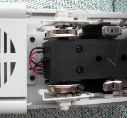
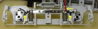
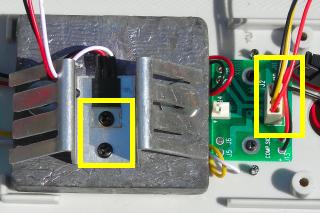
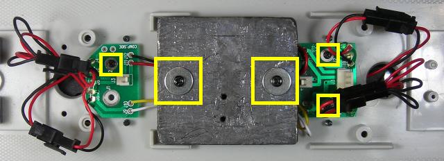
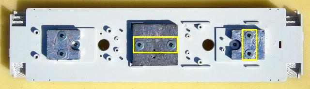
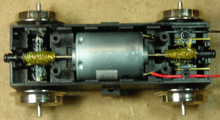
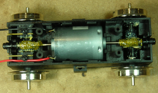
When the motors are wired, it would less confusing if the colour coding of the motor wires matched when fastened under the motor screw terminals of the Plug and Play Board. In order to accomplish this, one motor block has to be wired differently from the other. With the motor terminals facing each other, solder thirteen inches of black wire to the top terminal of the rear motor shown in the first image, and thirteen inches red wire to the bottom terminal. Solder eight inches of black wire to the top terminal of the front motor shown in the second image, and eight inches red wire to the bottom terminal.
Place the lash adjusters on the ends of the motor shafts. Place the motors back in the motor blocks. Ensure the tabs in the lash adjusters are in their slots in the ends of the motor blocks. If the worm gears on the motor shafts and the drive gears on the axles are properly meshed, the wheels should not turn. If required, lubricate the worm gears on the motor shafts with plastic compatible grease.
Lightly push the red and black wires into the outside channels left by the brass rods that were removed. Secure the wires and inside brass rods using the small screws and plastic washers in the small container. Set the top covers back on. If the covers are not fitting tightly, check to ensure the lash adjuster assemblies are seated properly. Fasten the covers back on with their screws.
Lay the frame upside-down on a soft surface. Undo the twelve, sideframe screws from the motor block cradles and set them in a small container. Lubricate the ends of the axles of both motor blocks.
Set the rear motor block with the thirteen inch wires in the rear engine block cradle. Slide a sideframe on the axles on one side of a motor block. Insert the two small, plastic pins on the inside of a sideframe into the matching holes of the motor block cradle. Fasten the sideframe to the cradle with three screws in the small container. Repeat the process for the other sideframe.
Set the front motor block with the eight inch wires in the front engine block cradle. Slide a sideframe on the axles on one side of a motor block. Insert the two small, plastic pins on the inside of a sideframe into the matching holes of the motor block cradle. Fasten the sideframe to the cradle with three screws in the small container. Repeat the process for the other sideframe.
Pass the wires for the rear motor block through the hole in the frame above it. Slip the wires under the center weight. Pass the wires through the hole in the front of the components platform.
Pass the wires for the front motor block through the hole in the frame above it. Pass the wires through the hole in the front of the components platform.
Strip 1/4 inch of insulation off the ends of the wires and tin them. Fasten the black wires under the motor screw terminal marked with a small triangle on the Plug and Play Board, and the red wires under the other motor screw terminal. Tug on each wire to ensure they are all fastened securely.

That completes the removal of the track power sliders, inspection and lubrication of motor and drive gears, as well as, the rewiring and installation of the motor blocks. Wash any black grease off your hands before proceeding, as it may stain the paint on the locomotive and will never come out your clothes.
THE CAB
Unsolder the red and black wires from the metal tabs at the back of the cab.
Draw the red and black wires through the hole in the front of the cab.
Unplug the two, white plastic connectors for the rear lights from the top of the circuit board in the nose of the hood. Detach the cab from the hood.
Draw the wires and connectors for the cab light and rear headlight back through the hole in the front of the cab.
Undo the two screws from the small circuit board. Turn the circuit board over and unsolder the black and red rear headlight wires from it. Place the circuit board and the attached wiring in the large Ziploc bag.
Wrap the wiring for the cab light around the two plastic posts on the front of the cab, and tape the connector to the side of the cab floor out of the way.
Solder and shrink wrap 18 inches of red wire to the red headlight wire. Solder and shrink wrap 18 inches of black wire to the black headlight wire. Pass the wires through the hole in the front of the cab. They will be wired to the Plug and Play Board after the battery switch has been installed and the cab fastened to the frame.
WIRING THE BATTERY SWITCH
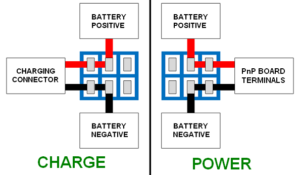
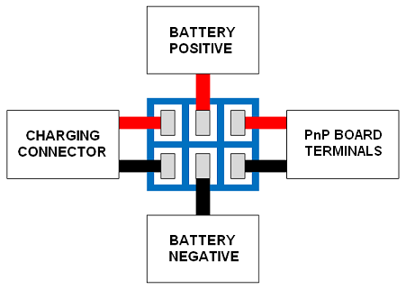
As the battery will be charged on-board, a double-pole double-throw (DPDT) switch is needed to toggle the battery between its charging connector and the Revolution receiver in the Plug and Play Board.
The DPDT center-off switch is available from All Electronics under catalog number MTS-12.
As it is easier to solder and shrink wrap the wires to the terminals of the switch before it is installed; place the switch in a small bench vise with the terminals facing up.
BATTERY CONNECTOR
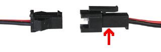
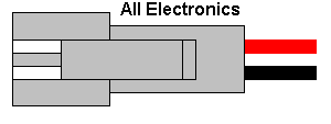
The male half of an All Electronics 2-wire connector set, shown on the right, has the same connector as an Aristo-Craft lithium-ion battery charger. It will be used to connect the battery to the center terminals of the switch.
The 2-wire connector set is available from All Electronics under catalog # CON-240.
CAUTION: The wires on the connector sets sold by All Electronics may not be positioned the same as the wires on the connectors of lithium-ion batteries and chargers. If not, click on the following link to see how to switch the positions of the AE Connector Set Wiring so that proper polarity is maintained.
DO NOT install the wires back in the connectors at this time. That will be done when the battery switch has been wired and installed.
Trim the wires of the male half of an AE connector set to 6 inches in length. Solder and shrink wrap the wires to the center terminals of the DPDT switch as shown in the following diagram.
BATTERY CHARGING CONNECTOR
The female half of an All Electronics 2-wire connector set, as shown on the left, has the same connector as an Aristo-Craft, lithium-ion battery. It will be used as the charging connector for the on-board battery.
Trim the wires of the female connector to 5 inches in length. Solder and shrink wrap them to the left terminals of the DPDT switch as shown in the following diagram.
PnP BOARD POWER WIRES
Cut an 18 inch length of red wire, and an 18 inch length of black wire. Solder and shrink wrap the wires to the right terminals of the DPDT switch as shown in the diagram above. These will be used to connect the battery switch to the Plug and Play Board to power the Revolution receiver.
Check to ensure all the red wires are soldered to one side of the switch, and all the black wires to the other.
INSTALLING THE BATTERY SWITCH
I usually find a place on a locomotive to install the battery switch so it is accessible, but hidden from view. Unfortunately on this locomotive there is no room on the fuel tank or bottom of the frame for a toggle switch. The owner also asked that it not be placed under the radiator door like I had done on a previous installation, as he found that cumbersome for his large fingers. His preferred choice was the back of the battery boxes behind the cab. I did consider a DPDT slide switch, but did have one with a long enough throw to extend beyond the thick battery box rear wall.
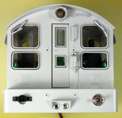
Toggling the switch towards the charging connector activates it. Toggling the switch towards the engineer powers the Revolution receiver.
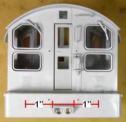
Set a ruler across the top of the step at the rear of the cab. On the edge of the ruler resting on the step, measure out 1 inch from either side of the step and place a pencil dot.
Pull the horn from the front of the cab, and place it in a small container. Remove the two screws holding the metal bracket to the front of the cab so it will lay flat while being drilled. Place the horn, metal bracket, and two screws in a small container for now.
On the right hand side (engineer’s side) of the battery boxes, slowly drill a hole at the mark for the battery switch using a 1/4 inch bit. Hold the cab firmly and do not hurry or the cab will climb the bit and distort the shape of the hole.
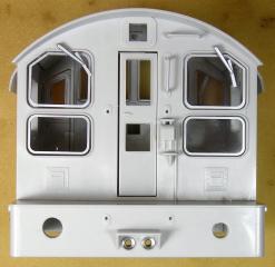
On the left hand side of the battery boxes, slowly drill a hole at the mark for the battery charging connector using a 5/16 inch bit.
Push the horn back into the front of the cab. Use the two screws in the small container to re-install the metal bracket.
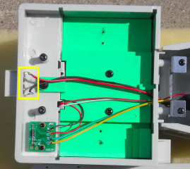
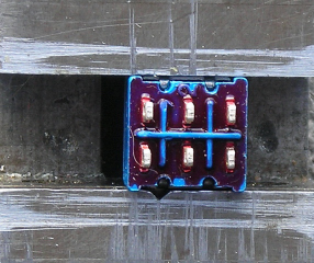
Fasten the switch in the 1/4 inch hole on the right of the cab. Looking at the inside of the cab wall, the charging connector wires should be on the left of the switch, and the PnP Board power wires on the right.
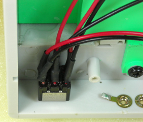
Spread the wings on the side of the battery charging connector up 90 degrees. With the locking nub facing up, wiggle the base of the connector through the hole on the left of the cab. To hold the connector in place, slide a 1/4 inch spade connector across its base. To hold the spade connector in place, place a dab of hot glue across it.
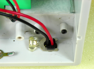
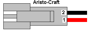
Check to ensure the small tabs on the metal terminals are raised slightly. If not, use an X-Acto knife blade to do so. Slide the terminal on the red wire into position 1, and the terminal on the black wire into position 2. Give the wires a light tug to ensure they are locked in place.
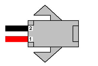
Pass the battery connector wires through the hole in the front of the cab. Check to ensure the small tabs on the metal terminals are raised slightly. With the locking tab on the male connector shell facing up as shown, slide the terminal on the red wire into position 1, and the terminal on the black wire into position 2. Give the wires a light tug to ensure they are locked in place.

Pass the PnP Board power wires through the hole in the front of the cab.
That completes the wiring of the battery switch.
INSTALLING THE CAB
Remove the two large screws from the posts in the center of the battery boxes. Remove the two small screws from the bottom of the metal bracket on the front of the cab. Place the cab on the frame.
Place the frame on its side on a soft surface. Use the two large screws to fasten the rear of the cab to the frame. Use the two smaller screws to fasten the metal bracket on the front of the cab to the frame.
The smaller screws will have to be inserted between the sideframes and the motor block.
Set the locomotive on its wheels.
WIRING THE PnP BOARD
Pass the wires for the rear headlight under the weight in the center of the frame. Pass the wires through the hole in the front of the components platform by the PnP Board screw terminals. Trim the wires to a length that will allow them to easily reach the screw terminals labeled HD COM and HD1. Trim an extra inch off the black wire.
Strip 3/16ths of an inch of insulation off the ends of the wires, and then flux and tin them. Fasten the end of the red wire in the screw terminal labeled HD COM.
Trim both leads of a 2 watt, 330 ohm resistor to 1/4 inch long. Solder and shrink wrap the end of the black wire to one of the resistor leads. Fasten the other lead in the screw terminal labeled HD1.
The resistors are available from Active Electronics under catalog number 2W133, although other electronic component suppliers should have them as well.
Pass the PnP Board power wires under the weight in the center of the frame. Pass the wires through the hole in the front of the components platform by the PnP Board screw terminals. Trim the wires to a length that will allow them to easily reach the screw terminals labeled TRK.
Strip 1/4 inch of insulation off the ends of the wires, and then flux and tin them. Fasten the end of the black wire in the TRK screw terminal marked with a small triangle. Fasten the red wire the other TRK screw terminal.
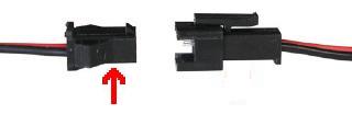
CAUTION: Check that the DPDT switch is in the center-off position. Ensure the colour coding of the wires on the lithium-ion battery connector and the connector soldered to the center terminals of the DPDT switch match. Plug the two connectors together.
Group the rear headlight, battery connector, and PnP power wires together behind the center weight using a small cable tie. Do not include the rear motor wires, as they have to be free to move with the motor block.
The wiring of the PnP will be completed when the factory components have been removed from the hood, and the front headlight wires have been extended. If you know how to program a Revolution receiver however, nothing stops you from testing the motors and the rear light.
REMOVING THE ELECTRONICS FROM THE HOOD
Unplug the black connector for the smoke board from the circuit board in the nose of the hood.
Undo the four screws that hold the smoke units and their circuit board to the top of the hood.
Place the smoke units, their circuit board, and four screws in the large Ziploc bag with the rest of the electronics.
Slide the U-shaped frame surrounding circuit board out from the nose of the hood. Slide the circuit board and its plastic switch plate out. The radiator door should also fall free.
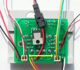
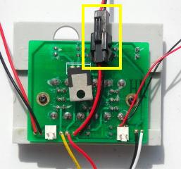
Undo the two screws that hold the circuit board to the plastic switch plate, and place them in a small container. Mark the base of the two pin header with the colour of one of the front headlight wires. Turn the circuit board over and unsolder the headlight wires. Tape the two screws in the small container in the holes of the circuit board. Place the circuit board in the large Ziploc bag with the rest of the electronics.
Set the switch plate, U-shaped frame, and radiator door aside for now. They will be re-installed when the front headlight has been wired.
That completes the removal of the factory electronics from the hood.
FRONT HEADLIGHT
Solder and shrink wrap a ten inch red wire to red headlight wire. Solder and shrink wrap a nine inch black wire to black headlight wire. This will allow enough slack for the hood to sit beside the frame when removed.
Place the hood on it side on a soft surface. With the headlight wires lying in the top of the hood, install the radiator door, the plastic switch plate, and the U-shaped frame back in the hood.
Strip 3/16ths of an inch of insulation off the ends of the wires, and then flux and tin them. Fasten the end of the red wire in the screw terminal labeled HD COM with the rear headlight wire.
Trim both leads of a 2 watt, 330 ohm resistor to 1/4 inch long. Solder and shrink wrap the end of the black wire to one of the resistor leads. Fasten the other lead in the screw terminal labeled HD2.
That completes the wiring of the PnP Board.
THE RECEIVER LINKING BUTTON
Part of the process required to link the Revolution receiver to its transmitter involves pushing a linking button. The button will be installed in the hole in the hood for the front exhaust stack. This will allow it to be accessible, but hidden when running the locomotive.
Place the linking switch complete with its nut and lock washer in the front exhaust hole of the hood as shown, and fasten it with hot glue.
Plug the linking button connector into header on the back of the receiver.
Remove the four screws from the hood. Re-install the hood and fasten it to the frame with the four screws.
Reinstall install the handrails to both ends of the locomotive.
THE RECEIVER
The Installation and Operation Manual for the Revolution Train Engineer is on the CD that comes with the set. The Revised Manual and other information is also available on the Aristo-Craft web site as an Adobe pdf file. To read or download the revised manual, click on the link.
Toggle the battery switch towards the engineer, and program the receiver in accordance with the instructions provided in the Installation and Operation Manual. To activate the linking button, insert a screwdriver or blunt end of a pencil in the front exhaust stack.
Place the locomotive on a piece of track or test stand. Test the motors and lights to ensure they respond properly to the throttle. After testing return the battery switch to its center off position.
CONGRATULATIONS! You have successfully installed battery power and radio control in your USA Trains NW-2 diesel switcher. ENJOY!
5 comments
Skip to comment form
Thanks for the great step by step instructions. The All Electronic part numbers were useful. What power jack did you use. Since my engine has not yet arrived, is the full tank for a speaker. The new 2.4ghz come with a sound unit.
Nice project description It has helped me in a similar NW2 install. Email me and I’ll send you some details concerning what I had to do different and why. Are the headlights 12v incandescent bulbs? That’s what they appear to me. Are the 330 ohm resistors intended to drop the voltage enough so the bulbs get only 12V? Do both ever light at the same time?
paul
The headlights are incandescent bulbs. The resistors drop the voltage and limit the current so they light properly, but do not burn out.
The Revolution receiver will activate only the lighting circuit of the headlight facing that direction of travel.
If you wanted both on, they would have to be wired directly to the battery and protected with voltage dropping, current limiting resistors.
The NW-2 fuel tank will hold a speaker. All the USA Trains fuel tanks I have seen to date hold a 2.5 inch Phoenix Sound speaker.
I am not sure what you meant by power jack. The male half of the All Electronics 2-wire connector is used to connect the battery. You can see a picture of it in the Battery Connector section of this project article.
The battery charger you use should have the same 2-wire connector, as it has to plug into the female half of the All Electronics 2-wire connector mounted on the back of the cab.
Hi Paul, I’m still enjoying the wealth of expertise shown in your articles. I’m about ready to convert my NW-2 and will try to stick closely to the plan. Your conversion plan for the GP-30 was helpful on my GP-38, but I have not finished with the lights yet. Right now I’m having trouble with an Aristo battery which appears be defective. Not content to take on one problem at a time. Having fun at 86!
Barry