This article describes the conversion of a Bachmann Heisler to Revolution R/C with generic steam sound and lithium-ion battery power. A lot of work reverse-engineering the locomotive’s wiring and electronics was done by George Schreyer, and can be found at his website here: http://www.girr.org/girr/tips/tips9/heisler_tips.html. His wepage covers the installation of track-powered DCC, however I found the information invaluable when performing this conversion, and acknowledge my debt to him. Here, I describe two versions of the conversion, one that retains the Bachmann electronics board, and one that eliminates it.
Components and materials needed:
-
- Revolution control system (includes linking button and speaker leads)
- Lithium-ion battery (I am using a 22 volt six-cell pack in a 2×3 configuration)
- Two-pin connecting plug, 1 pair.
- Small DPDT switch (centre-off is optional)
- Socket compatible with your battery charger plug. (A CircuitTest 2.1mm power jack matches the charger that came with my Revolution system).
- “Sugar cube” speaker
- Fuse holder + 2 amp fuse (I am using a cylindrical glass fuse)
- Hookup wire, red and black colours (22 AWG is adequate).
- Solder, heatshrink tubing (size appropriate to small-gauge wire), double-sided foam tape
Notes:
-
- I have not attempted to make the conversion easily reversible.
- I assume the reader is comfortable with wiring and soldering.
Working on the locomotive
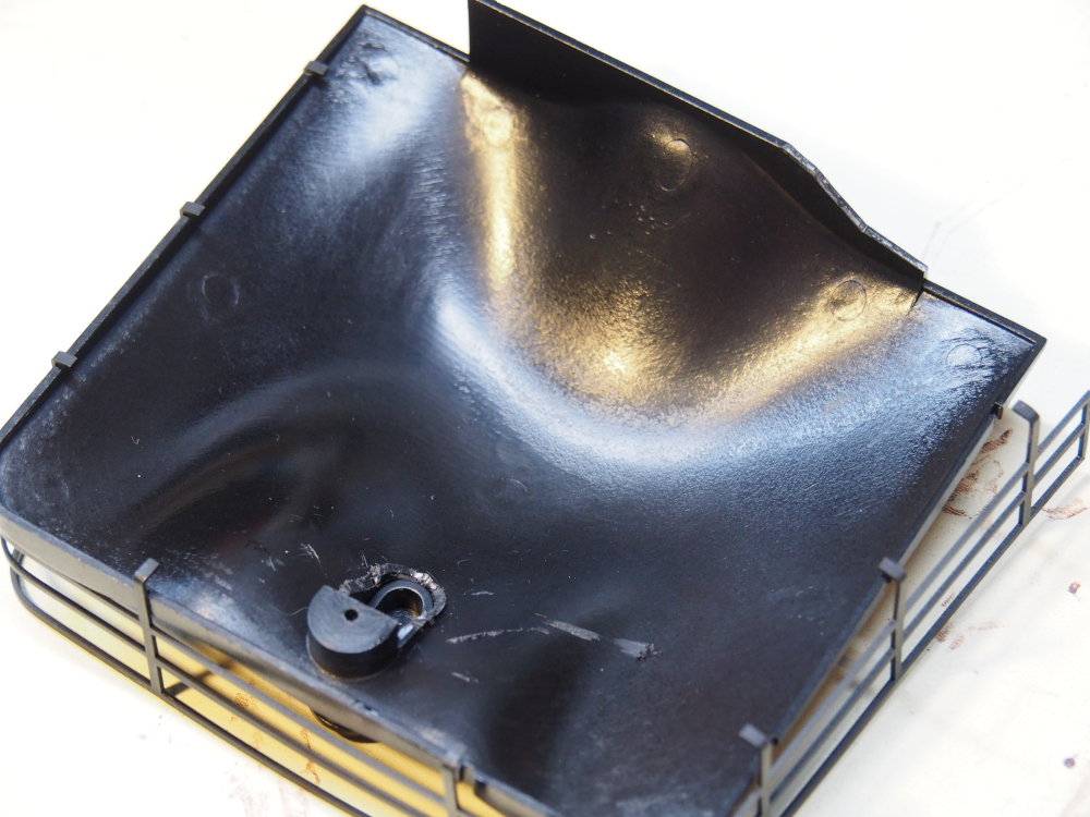
The “works” are hidden in the coal bunker, and the coal load must be removed to access them. This is held in place by a screw under the water hatch. The load fits tightly, but with the screw removed it is possible to wiggle it out (the little fence comes loose from the coal). The screw also holds the body of the coal bunker on, so it should be reinstalled after the load is removed. The coal load can be put back in with the screw in place.
The body of the bunker, as well as the cab roof and walls can be removed by locating and removing a number of very small screws, however it is not necessary to do this to perform the conversion (though you may wish to remove the cab roof to install the crew).
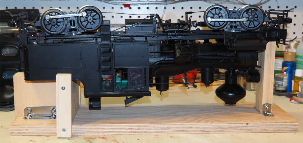
For the purpose of working on the underside of the Heisler, I found it useful to have a work cradle that holds the locomotive stable, and prevents damage to topside details. I knocked this one together out of scrap lumber (note that this is intended to be used with the coal load removed):
Both Conversions
Whether or not you are retaining the Bachmann electronics board, begin by wiring up the battery and power components.
The locomotive comes with a set of diagrams showing exploded-parts views and a wiring diagram. The Bachmann wiring diagram is a bit hard to follow, so I have redrawn it in Figure 1, with the wire colours shown (white is here depicted in grey). The reversing switch and the smoke switch are located behind the smoke box hatch at the front of the boiler.
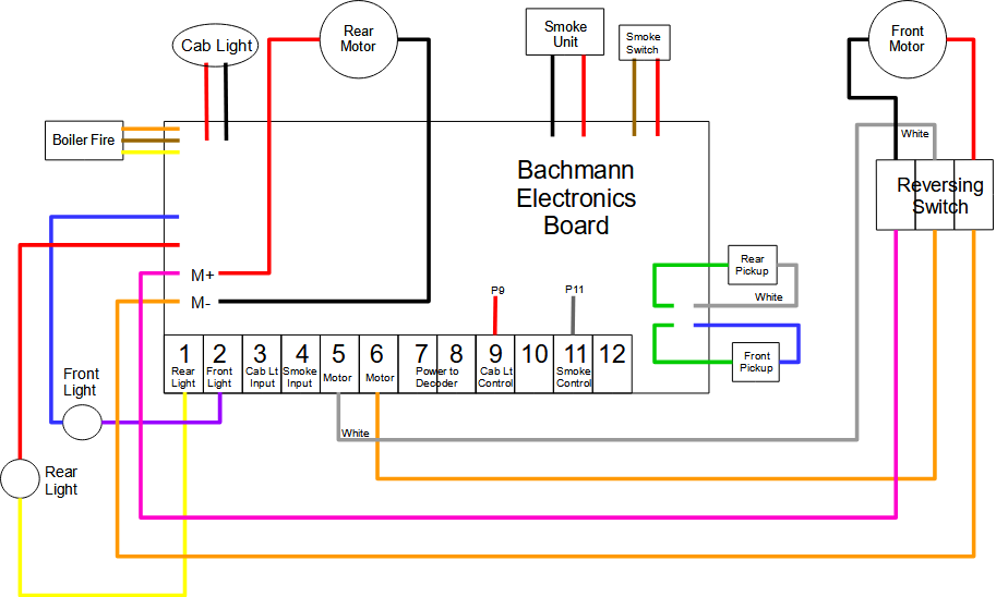
Caution: Some wire colours are used more than once. Before cutting or reconnecting any wire, be sure you have the correct one!
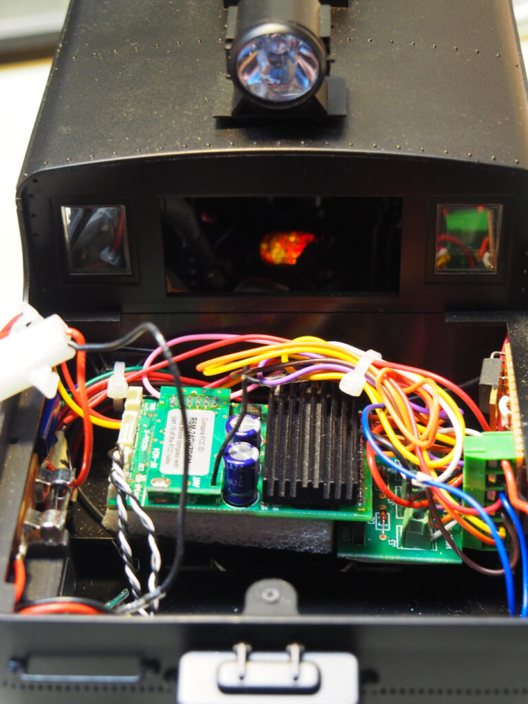
With the coal load removed, the electronics board and the weight become visible. As you can see, there is not much space in the bunker. The components to be installed here are:
-
- Battery
- Revolution board
- Fuse & holder
- Linking button
- Charging socket
- Run/Charge switch
- Speaker
The weight must be removed to make room for the battery (this is not a problem as the weight of the battery makes up for it). A smaller battery would probably fit on top of the weight. The weight is fastened down by two screws, and is easy to remove.
Battery Connections
The battery is connected through a two-pin plug connector, to make it possible to remove it without cutting or de-soldering wires. If your battery did not come with a connector installed, then install a connector of your choice. I am using this style: [pic of connector]
Danger: Shorting out a lithium-ion battery can result in fire or explosion! Do not cut both wires at the same time with the same tool. Take care to perform the plug installation in such a way that you never have bare conductors exposed on both battery leads at the same time.
To make it easier to work on the electronics, the battery should be installed after everything else is finished. I applied carpet tape to the underside of the battery to prevent it from moving around too much.
Caution: Carpet tape is not strong enough to hold the battery in place when the locomotive is turned upside down, so be sure to keep a spare finger on the battery when doing so. Also note the block of wood on the work cradle (picture above) under the rear of the locomotive, which prevents the battery from falling out.
It is easiest to assemble the wiring harness connecting the other half of the battery plug, fuse, charging plug, and run/charge switch on the workbench, before installing these components in the locomotive. This avoids the risk of damaging the locomotive plastic with a hot soldering iron. Solder these components together using hookup wire as shown in Figure 2:
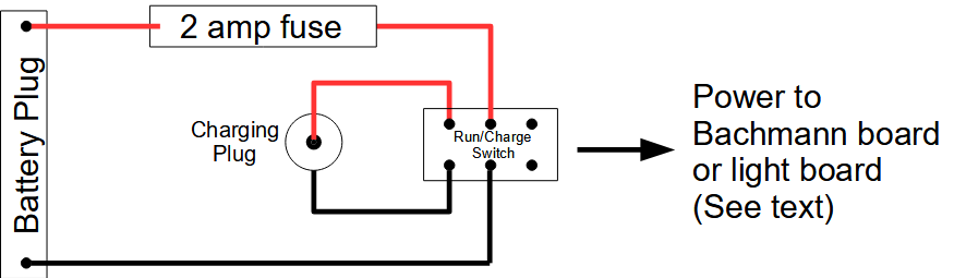
Note that in the diagram I have followed the convention of using red wire for positive and black for negative. In the kind of socket most often used, the centre post is usually the positive terminal, however check that this matches the polarity on your charger plug.
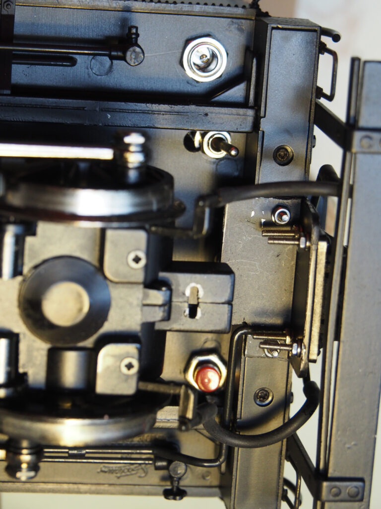
The charging socket and switch are installed in the floor of the bunker, to be accessed from underneath the locomotive. The linking button should also be installed at this time. They need to be close to the rear wall of the bunker to be out of the way of the battery. Drill holes (of sizes matching the respective components) in the locations shown in the photos below:
Fuse holder: The fuse holder is attached to the left side wall of the bunker using foam tape, at a location that makes it easy to change fuses
Speaker: The Revolution kit comes with a twisted lead for the speaker. Solder the free ends of this to the speaker terminals. Install the speaker below the fuse holder with foam tape, as shown below:
Modifying the coal load: The plastic under the water hatch interferes with the battery. Use a small razor saw to cut it away as shown below. I also found it necessary to chew away some plastic at the front of the load to clear some wiring and components.
Conversion #1: With Factory Electronics
Track power is supplied to the Bachmann electronics board by the two green wires and the white and blue wires (see Figure 1). The green wires are connected together on the board, and the white and blue are also connected together, which makes it easy to repurpose them to supply battery power to everything. The wires enter the bunker from under the floor. Cut all four of them such that there several inches left attached to the circuit board (Note: this is one of the steps that makes it difficult to revert the locomotive to track power). The cut ends coming from the track pickups should be taped out of the way, such that the ends cannot short together (in case the locomotive is ever operated on powered track). Solder the blue and one of the green wires to the remaining terminals on the DPDT switch (blue is the positive lead).
Revolution Board
The Revolution board can sit loose on top of the Bachmann board.
Caution: Put a thin sheet of plastic or other insulating material under the Revolution to prevent shorts between the boards.
Power: Strip the ends of the remaining power wires (the white and green wires soldered to the Bachmann board) and insert them into the input terminals of the Revolution.
Headlight connections: Remove the purple (front headlight) and yellow (rear headlight) wires from terminals 2 and 1 of the Bachmann board and insert them into the HD1 and HD2 terminals, respectively, of the Revolution. The C terminal provides power to run the headlights, which are turned on by grounding HD1 and HD2. However, positive power for the lights is already provided by the Bachmann board (which also provides the ballast resistor), so C is left unused in this application.
Motor connections: Remove the white and orange wires from terminals 5 and 6 of the Bachmann board, and insert them into the MOTOR terminals of the Revolution board. If you later find that the locomotive runs backwards relative to the throttle setting, then reverse these wires (or flip the reverse switch on the locomotive, or program the reversal in your throttle configuration).
Plug the linking button and speaker leads into the appropriate sockets on the Revolution board.
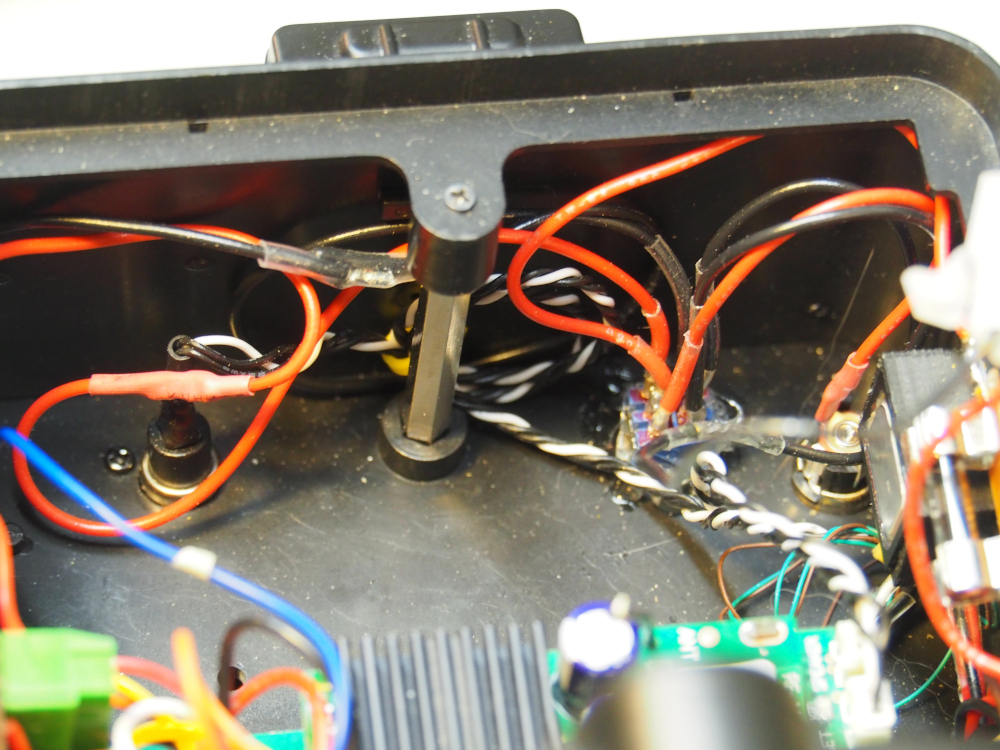
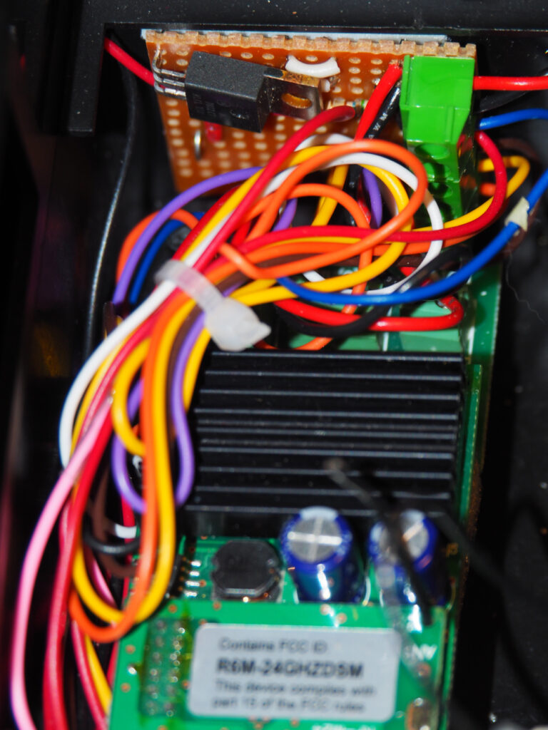
Here is the final wiring after conversion:
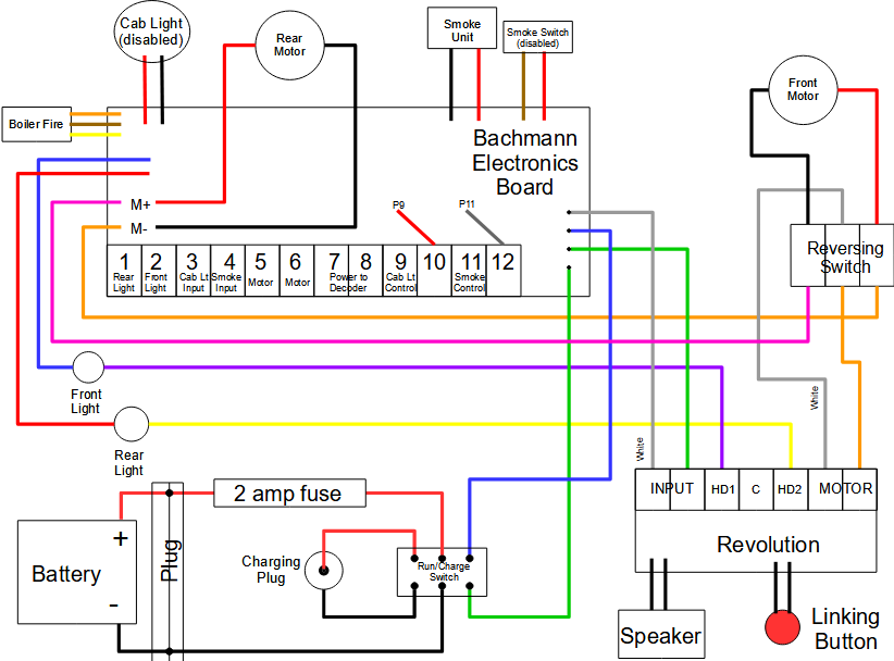
Put the battery in its place and plug in the power connector. Flip the DPDT switch to the Run position and set up the throttle according to the Revolution instructions. The conversion is now complete, and the coal load can be reinstalled. The cab light and smoke unit are still operable from the Bachmann board.
Conversion #2: Eliminating Factory Electronics
Under conversion #1, the only pieces of circuitry on the Bachmann board still being used are the ballast resistor for the headlights, and the circuit that drives the boiler fire flicker (personally, I don’t care for smoke). Space in the bunker is tight, and it seems silly to waste it on a large board that is not doing much. This section describes replacing the Bachmann board with a small board that takes over these functions. The final wiring is as shown below:
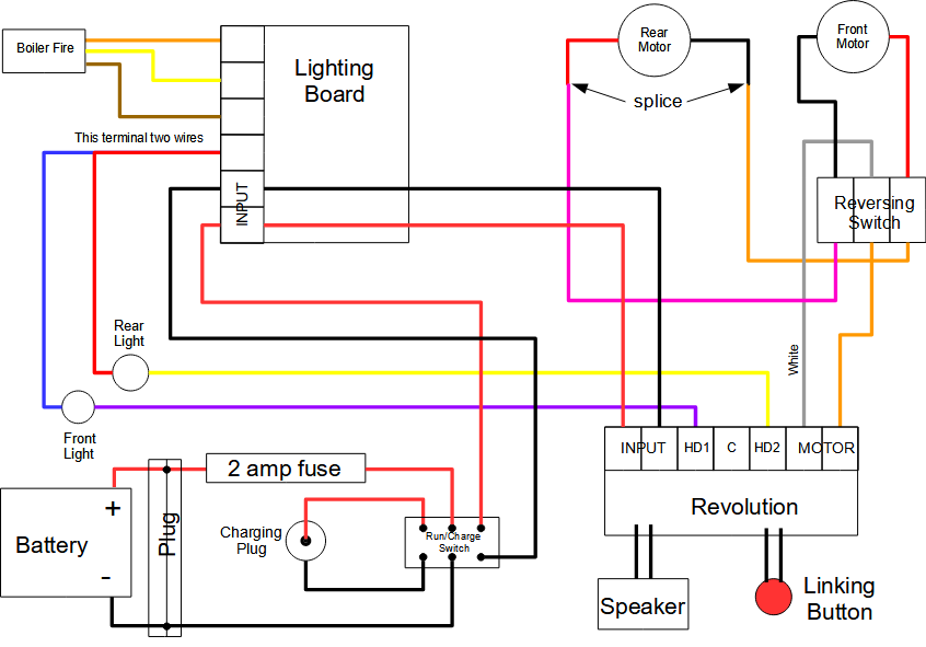
Note: This conversion does not support the cab light or smoke unit. The Revolution kit comes with components to support a smoke unit, however I did not install them. The cab light could probably be made to work using an auxiliary output of the Revolution, and a bit of additional electronics.
Materials:
-
- Perf board
- Terminals (six total)
- Resistors: 3 each of either 560 ohm 1/4-watt or 1200 ohm 1/2-watt.
- 7812 12Vdc voltage regulator (only needed if the 1/4-watt resistors are used)
Removing the Bachmann Board
Caution: This is the step that makes it really hard to restore the locomotive to factory condition. Only proceed if you’re sure you want to do this.
Note: In the next step, it is prudent to tape and label each bundle of wires as you remove it so that they are easy to identify later. The wires which will be reused are: rear motor, reversing switch, boiler fire, and headlights.
Remove all wires from the screw terminals on the Bachmann board: motor power (white/orange), front headlight (purple), rear headlight (yellow).
Snip off or desolder all the wires which are soldered to the board: cab light (red/black), rear motor (red/black), smoke unit (red/black), smoke switch (red/brown), headlights (red/blue), reversing switch (violet/orange), boiler fire (orange/brown/yellow) and track pickups (green/white/blue). Remove the circuit board by unscrewing the two screws holding it down. Tape all unused wires out of the way. Remove the Bachmann electronics board.
Light Board
The light board is a piece of perf board about one inch square. Install the terminal connectors along one edge, and wire up the board as shown below:
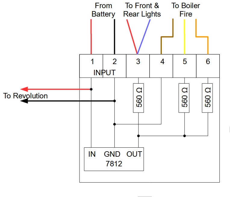
Note: Why am I using the 7812? Because I don’t happen to have 1/2-watt resistors on hand, but I do happen to have a complete set of 1/4-watt, and a junk drawer full of 7812’s. That is the only reason. You may want to obtain the 1200 ohm 1/2-watt resistors instead, in which case you don’t need the 7812. The 1200 ohm resistors would be soldered directly between the foil connected to terminal 1 and the foils connected to terminals 3, 5 and 6.
Power connections: Solder red and black hookup wires to the remaining terminals on the DPDT switch, and insert the other ends into the terminals 1 and 2 of the light board. Solder red and black hookup wires to the perf board behind terminals 1 and 2 respectively, and connect the other ends to the input terminals of the Revolution.
Headlight connections: Both headlight leads (blue & red) connect to terminal 3 on the light board. This supplies positive, current-limited power to them, and they are controlled by grounding the HD1 and HD2 terminals on the Revolution. Connect the purple and yellow wires (previously connected to terminals 1 and 2 of the Bachmann board) to HD1 and HD2 respectively.
The boiler fire leads connect to terminals 4, 5 and 6 as shown. Note that this circuit does not support the fire flicker (which I personally don’t care for). The fire functions as a simple power-on indicator (leave the firebox door open).
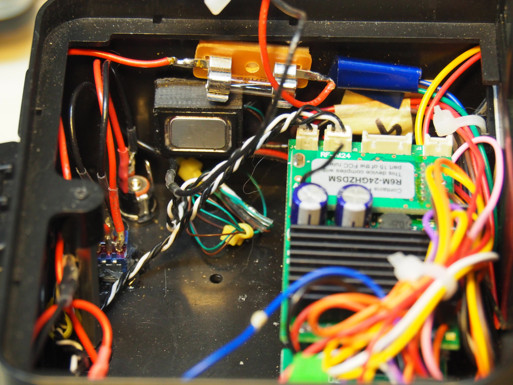
Install the light board on the bunker wall with foam tape as shown below:
Motor connections: Splice the violet and orange wires (from the reversing switch) to the rear motor leads (red and black respectively, refer to the diagram). Insulate the splices with heatshrink tubing.
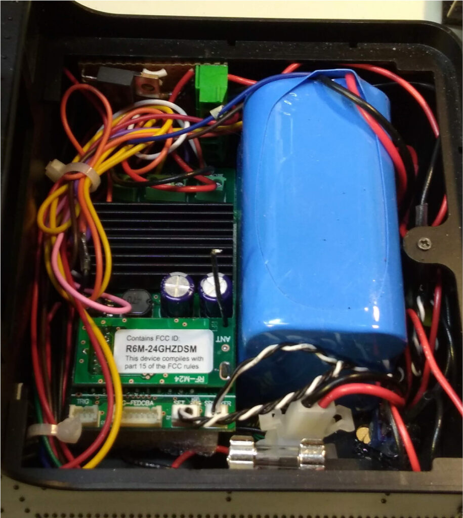
Put the battery in its place and plug in the power connector. Flip the DPDT switch to the Run position and set up the throttle according to the Revolution instructions. The conversion is now complete, and the coal load can be reinstalled. The contents of the bunker should now resemble the pictures below (in the left photo the battery is not installed):