UPDATED 30 DECEMBER 2012
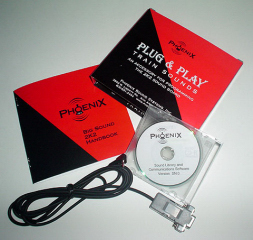
Sound really adds an extra level of realism and enjoyment to any locomotive. This article details a method used to add a Phoenix Sound P8 to a battery powered and radio controlled, Aristo-Craft FA-1.
The article may appear long because it detailed and includes lots of pictures. But if you take your time and follow it step-by-step it is not difficult, and the results are well worthwhile. Although an FA-1 was used for this installation, the instructions might be used as a guide to install a Phoenix Sound P8 in other Aristo-Craft 4-axle diesels.
OPENING THE LOCOMOTIVE
Place the locomotive upside down on a soft engine cradle taking care not to damage the horns.
Remove the 10 screws outlined in yellow that hold the shell to the frame and place them in a small container.
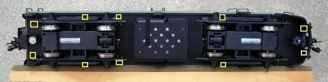
- 2 are at the very front under the pilot
- 2 are under the rear of the front truck
- 4 are under front of the rear truck
- 2 are at the very rear of the frame
Remove the small screw holding each of the mud flaps to the rear of the shell. Place the mud flaps and screws in the small container.
Lift the frame from the shell from the front to the back. If it sticks, check to see if the ends of any grab irons or railings have been pushed inside the shell. Set the frame right side up beside the shell.
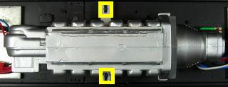
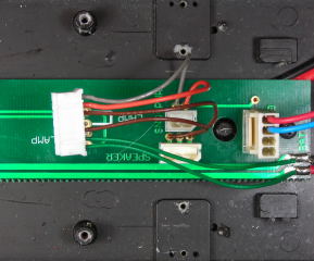
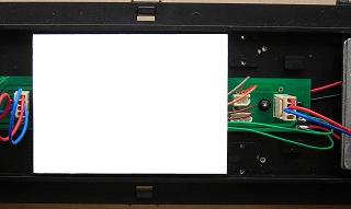
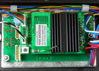
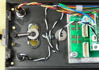
If the instructions from the previous article were followed, the components and wiring should look like the following picture.
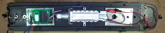
Unplug the 2 connectors from the rear of the Plug and Play printed circuit board PCB-01.
Remove the 2 screws holding the plastic diesel engine to the frame. Place the engine in the Ziploc bag used to store the components removed from the locomotive when it was converted to battery power and radio control. Place the two screws back in the frame, as they will be used later.
Unplug the speaker from the 3-pin header on the printed circuit board PCB-02.
Fasten the rear mud flaps back on the shell. Fasten the 10 screws back in the shell so they do get lost or mixed up with others. Set the shell aside for now.
Remove the 4 screws outlined in red from the frame. Remove the lamps and their holders. Fasten the screws back in place.
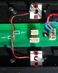
Remove the three screws from the printed circuit board PCB-02 and place them in a small container so they do not get lost or mixed up with others. Unsolder the four wires for the interior lamps from the bottom of the board. Place the lamps, holders, and their four screws in the Ziploc bag.
Unplug the battery pack.
Turn the frame over and remove the six screws from the base of the fuel tank.
Draw the battery connector through the square hole in the frame. Set the battery pack and fuel tank aside for now. Fasten the 6 screws back in the frame so they do not get lost or mixed up with others.
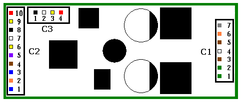
THE P8 SOUND BOARD WIRE CONNECTOR C1
The P8 connector C1 has 6 wires: two green, two brown, an orange and a gray.
All of these wires will be soldered to the front end of printed circuit board PCB-02. Cut all 6 wires to 2 1/2 inches in length. Remove an 1/8 on an inch of insulation off the ends of all the wires, and tin them.
The two green wires (C1:1 and C1:2) are used to power the sound board. Solder C1:1 with the positive battery wire, and C1:2 with the negative battery wire.
The sound board will be powered whenever the battery switch is toggled to power the receiver in the Plug and Play socket.
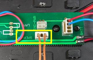
The two brown wires (C1:3 and C1:5) are used to power the speaker. On the PCB-02 there is 3-pin header labeled SPEAKER. The speaker’s connector will be plugged into this header when the locomotive is re-assembled. Above the header are 3 holes which are connected through traces on the printed circuit board to the header.
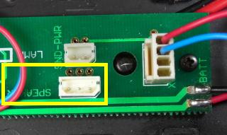
Slip the end of brown wire C1:3 in the outside hole on the left, and C1:5 in the outside hole on the right. Flux and solder them to the bottom of printed circuit board.
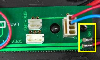
The orange and gray wires (C1:6 and C1:7) are used to measure the voltage of the motors and adjust the sound as the locomotive accelerates and decelerates. On PCB-2 there is a 2-pin header labeled “SND-PWR”. Above the header are 2 holes which are connected through traces on the printed circuit board to the header.
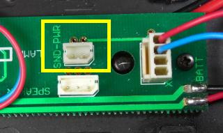
Slip the orange wire in the hole on the left, and gray wire in the right. Flux and solder them to the bottom of the printed circuit board.
Fasten PCB-02 back on the frame with the 3 screws in the small container. If the advice from the previous battery power article was taken, the screw at the end of the circuit board near the battery pack wires is longer. Do not tighten it down too firmly or the circuit board may crack.
That completes the installation of the C1 connector wires. The connector will be plugged into header C1 on the sound board when it is installed.
THE P8 SOUND BOARD PLATFORM
The P8 sound board will be mounted on a styrene platform in place of the plastic diesel engine.
From a 1/16 inch thick piece of styrene sheet, cut a piece 2 1/2 inches wide by 4 5/8ths inches long.
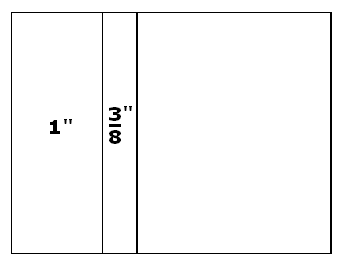
Cut three pieces, 3/8ths of an inch wide by 2 1/2 inches long, off the end of the platform. Glue the 3 pieces together in a stack 3/16ths of an inch high. On the bottom of the platform, draw a line 1 inch in from the left edge as shown. Glue the stack inside the line as shown.
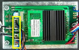
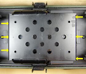
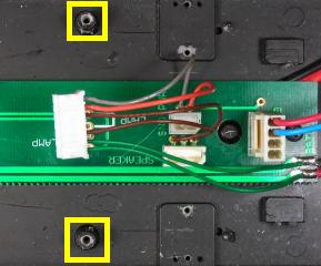
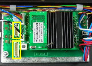
Remove the screws from the posts outlined in yellow and place them in a small container. They will be used to hold the sound board platform in place. Place a 3/64ths inch bit in a pin vise down the through hole in one of the posts. The battery pack has been removed right? Drill a hole through the frame taking care not to damage the threads in the post. Repeat for the process for the other post.
If the motor wires are taped to the frame in this area, remove the tape and move them back out of the way. Tape the platform to the frame as shown. The stack on the bottom of the left end of the platform should rest on the square posts on the frame. The right end of the platform should rest on the 2 posts that once held the plastic diesel engine. The platform should be level and evenly spaced between the rails on the frame.
From the bottom of the frame, place the 3/64ths inch bit in the pin vise up the through hole in one of the posts. Give the pin a vise a few turns to place a mark in the bottom of the styrene platform. Repeat the process for the other post.
Remove the styrene platform and tape from the frame. Drill a hole through the platform with a 3/32 inch drill bit at each of the marks.
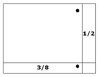
On the top of the platform, draw a line 1/2 inch in from the right edge, and 3/8ths of an inch up from the bottom edge as shown.
Before the platform can be fastened to the frame, the battery pack and fuel tank must be installed. Remove the three screws from printed circuit board PCB-2 and place them in a small container so they do not get lost or mixed up with others.
Turn the frame over and pass the battery pack connector through the square hole closest to the cab. Remove the six screws from the frame and fasten the fuel tank back on to it.
Turn the frame over. Fasten PCB-02 back on the frame with the three screws. Do not over-tighten the longer front screw covering the battery pack wires or you may crack the printed circuit board.
Securely fasten the P8 sound board platform to the frame with the two screws that held the plastic diesel engine in place.
The sound board will fastened at the corners with hot glue to styrene strips glued to the platform. This will hold the sound board more securely than either double-sided tape or Velcro, and allow air to cool the components on the bottom of the board. From a 1/8 x 1/4 inch styrene strip, cut two pieces 2 1/2 inches long. Cut two more pieces exactly 13/16 of an inch long.
Glue one of the longer strips of styrene on edge inside the lines as shown. Using the smaller pieces as spacers, fasten the other longer piece on edge exactly 13/16 of an inch up from the first. Remove the spacers and save them for other P8 installations.

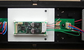
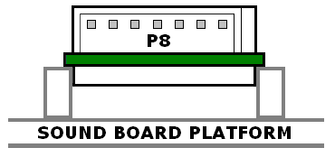
With the 7-pin header C1 facing the cab, place the sound board on top of the two strips mounted on the styrene platform. The components on the bottom of the sound board should sit in between the styrene strips, while the P8 circuit board sits on top of the inside edges.
Fasten the sound board to the strips with a small dab of hot glue at each corner.
Plug wire connector C1 into the header with the serial number on the end of the sound board.
TRIGGER WIRE INTERFACE BOARD
The P8 sound board wire connector C2 has 9 wires.
Three of these wires (C2:8, C2:9, and C2:10) come with a momentary switch attached to raise and lower the sound volume. But hiding the switch so it does not alter the appearance the locomotive, does not allow it to be accessed while operating. Fortunately Phoenix Sound has posted a diagram of a small circuit that can replace the switch and allow the volume to be raised and lowered with two trigger keys on the Revolution throttle. The circuit uses a resistor and a transistor which can be mounted on a small circuit between the sound board and receiver.
The circuit board also has enough screw terminals to connect all 12 trigger wires between the receiver and the sound board without soldering and shrink wrapping each pair together.
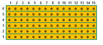
The trigger wire interface board is made from a straight trace perf board available from All Electronics under catalog number ECS-4.
Score both sides of the perf board and snap off a piece 6 traces by 15 columns across. Sand the edges smooth.
Fasten two, 6-position, screw terminal blocks, or any combination of terminal blocks that will cover all 6 traces, to each end of the component (green) side of the perf board with super glue. The pins of the blocks should be in columns 2 and 14, and the openings for the wires should face out.
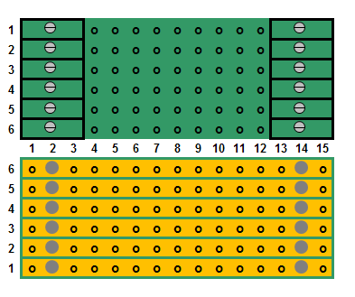
The terminal blocks are manufactured by Phoenix Contact and are available from Mouser Electronics under the manufacturer’s part number 1725698 for the 6-position version.
Flip the perf board over. A good soldering iron of at least 40 watts and thin solder wire will be required. The pins of the terminal blocks and traces must be properly fluxed and heated before the solder is added and allowed to flow. Solder the pins of the terminal blocks to the board.
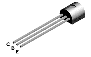
The volume control circuit uses a 1K resistor and a 2N3906 transistor which can be purchased from All Electronics under catalog numbers 293-1K and 2N3906.
The 2N3906 transistor has three leads. If you place the transistor flat side down with the leads to the bottom, the leads from left to right are the collector, base and emitter. That’s all you have to know about this device.
Remove 1/2 an inch of insulation from a piece of yellow 22 gauge wire. Cut a piece of insulation to exactly 3/16ths of an inch. Slip the cut piece over the left lead (collector) and push it flush against the bottom of the transistor.
Remove 1/2 an inch of insulation from a piece of red 22 gauge wire. Cut a piece of insulation to exactly 3/16ths of an inch. Slip the cut piece over the right lead (emitter) and push it flush against the bottom of the transistor.
These leggings will set the transistor at the right height above the perf board for soldering and ensure they do not touch the center lead (base) when it is bent to fit. They are also colour matched to the sound board’s volume control wires C2:9 and C2:10.
Bend the center (base) lead out 45 degrees from the round side of the transistor. With the flat side of the transistor facing the terminal block, trial fit the two outside leads (collector and emitter) in column 11 on the component side of the perf board. The yellow lead (collector) should be in trace 5 and the red (emitter) in trace 6. Bend the bottom of the center (base) lead until it fits in column 9 of trace 6 to the left of the transistor as shown in the following diagram. Fasten the bottom of the leggings to the perf board with a bit of super glue to hold the transistor in place.
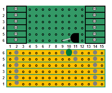
Flip the perf board over. Flux and solder the three leads of the transistor to the perf board, and trim them. Break open trace 6 between the emitter and base leads as indicated with the big green dot, using a 1/8 inch drill bit in a pin vise.
Bend the leads of a 1K ohm resistor so they will fit in the holes of columns 4 and 8 on the component side of the perf board. Insert it in trace 6 of the board as shown.
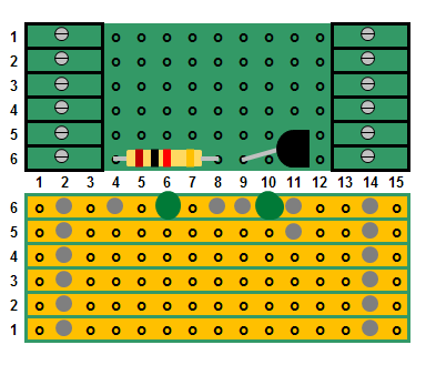
Flip the perf board over. Flux and solder it in place, and trim the leads. Break open trace 6 between the leads as indicated with the big green dot, using a 1/8 inch drill bit in a pin vise.
Clean the perf board with flux remover. A small hobby awl run between the soldered traces will remove excess flux and solder.
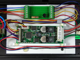
Fasten two, 1/4 inch, nylon spacers to the platform next to the sound board with a dab of hot glue. Apply a couple of runs of hot glue across the styrene platform, and fasten the trigger wire interface board next to the spacers.
The nylon spacers can all be purchased from All Electronics under catalog number SP-42.
That completes the installation of the trigger wire interface board. Now it will be wired to the receiver and sound board.
REVOLUTION RECEIVER TRIGGER WIRES
The Revolution receiver comes with a wire connector with 6 trigger wires, and a black ground wire. Plug the connector into the header on the back of the receiver labeled “A” to “COM”.
Fasten with a dab of hot glue, two 1/4 inch long, nylon spacers to the rear weight beside the Plug and Play circuit board. Run all the trigger wires through the two spacers.
Fold the black ground wire back through the spacers out of the way. Cut the remaining triggers wires to a length that will easily reach the screw terminals on the left end of the trigger wire interface board. Strip 3/16ths of an inch of insulation off the ends of the 6 trigger wires, and tin them.
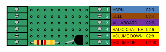
These six wires will be used to trigger the horn, bell, “all aboard” call, and radio chatter, as well as, to lower and raise the sound volume. To do this, they must be connected to the corresponding wires of the P8 sound board connector C2. Unfortunately the wire colours do not match, so a chart like this one is needed to connect the wires properly.
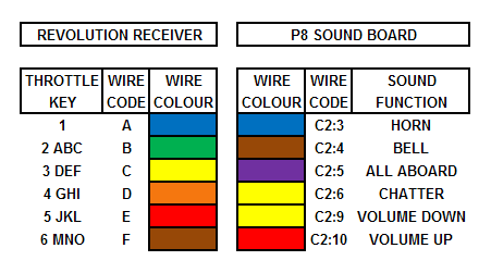
Although the wire colours do not match, in this chart the wire codes for the sound board and receiver are in ascending order, as are the throttle key designations.
Turn all the screws on the terminals of the trigger interface board counterclockwise to open the wiring slots.
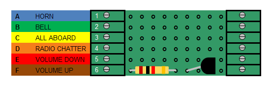
- On the left hand side of the trigger wire interface board fasten:
- the blue wire A for the horn in screw terminal 1,
- the green wire B for the bell in screw terminal 2,
- the yellow wire C for the “all aboard” call in screw terminal 3,
- the orange wire D for radio chatter in screw terminal 4,
- the red wire E to lower the sound volume in screw terminal 5, and
- the brown trigger wire F to raise the sound volume in screw terminal 6.
That completes the installation of the Revolution receiver’s trigger wires.
THE P8 SOUND BOARD WIRE CONNECTOR C2
Plug the wire connector C2 into the 10-pin header on the left end of the sound board. The C2 connector has 9 wires, but only 6 are used in this installation as that is the maximum number of sound functions the Revolution receiver can trigger at this time.
Cut the momentary switch off the ends of the black, yellow, and red wires (C2:8, C2:9, and C2:10), and set it aside. Cut the bare wire tips off the blue and orange wires (C2:1 and C2:2). Hot glue the blue, orange, and black wires (C2:1, C2:2, and C2:8) out of the way.
Pass all remaining 6 trigger wires through the two spacers. Cut them to a length that will easily reach the screw terminals on the right end of the trigger wire interface board. Strip 3/16ths of an inch of insulation off the ends and tin them.
Two of the wires (C2:6 and C2:9) are yellow, and must be installed under the proper screw terminals.
- On the right hand side of the trigger interface board fasten:
- the blue wire (C2:3) for the horn in screw terminal 1,
- the brown wire (C2:4) for the bell in screw terminal 2,
- the purple wire (C2:5) for “all aboard” call in screw terminal 3,
- the yellow wire (C2:6) for the radio chatter in screw terminal 4,
- the yellow wire C2:9) to lower the sound volume in screw terminal 5, and
- the red wire (C2:10) to raise the sound volume in screw terminal 6.
That completes the wiring of the trigger wire interface board.
THE P8 SOUND BOARD WIRE CONNECTOR C3
On the end of P8 wire connector C3 is the programming jack for the Phoenix Sound Computer Interface. This accessory is used to customize sound files or upload upgraded ones. Every sound function can be modified or replaced to suit the locomotive owner’s personal preferences.
The programming jack will be mounted in the back of the frame opposite the remote linking button.
Drill a hole using a 5/16 inch bit at the back corner of the frame opposite the remote linking button. Remove the nut for the P8 programming jack from it wires, and pass the connector and wires up through the hole in the frame. Slip the nut back over the connector and wires, and use it to fasten the programming jack in place.
Pass the wires across the top of the Plug and Play circuit board, and plug the connector into the 4-pin header C3 on the side of the P8 sound board.
That completes the installation of the Phoenix Sound P8 sound board.
ASSEMBLING THE LOCOMOTIVE
Remove the ten screws from the shell, and place them in a small container.
Place the shell beside the frame, and plug the 4-wire and 5-wire connectors into the rear of the Plug and Play printed circuit board PCB-01.
Plug the speaker back into the 3-pin header labeled “SPEAKER” on printed circuit board PCB-02.
Set the shell on top of the frame. Place the locomotive on a set of rollers, test stand or track so the wheels can turn freely.
Turn the Revolution throttle on and select the locomotive. In the Assign Functions menu check to ensure that Function 2 for the bell is set to “latched”.
Be aware that throttle key “5 jkL” will lower the sound volume. Toggle the battery pack switch to the run position.
Test the locomotive and sound board to ensure they respond properly to the throttle.
- From a stop, the horn should automatically toot twice in forward, and three times in reverse.
- Throttle key 1 triggers the horn,
- Throttle key 2 turns the bell on and off,
- Throttle key 3 triggers the “all aboard” call sound,
- Throttle key 4 triggers radio chatter,
- Throttle key 5 lowers the sound volume, and
- Throttle key 6 raises the sound volume.
After testing, return the battery switch to its center off position.
Use the 10 screws in the small container to fasten the shell to the frame.
Congratulations! You now have an FA-1 with on-board: battery power, radio control, and sound.