
Plastic switch throws did not stand up well here in our northern climate. Over the years we tried a number of different store-bought replacements, but none had the durability we sought.
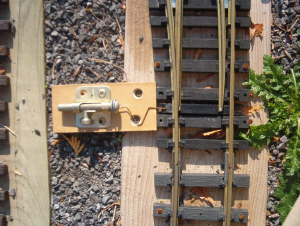
A number of years ago, we adapted brass, barrel-bolts as switch throws. They proved to be rugged enough for both our climate and constant use during our railway operations.
 |
 |
They were inexpensive, easy to assemble, and required no maintenance except for an occasional spray with some silicon lubricant. The V spring provided both compression and tension to hold the switch points against the rail in either direction. It was made with tempered steel wire, sometimes referred to as piano wire, and was easily formed with pliers.
When Mercer siding was built, it was realized that throwing switches on the ground was hard on our creaky old backs and knees. As the siding could not be raised, the switch throws were.
 |
 |
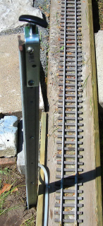
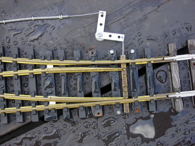
T bars were driven into the ground near the switches. An L shaped bracket was bolted to the top and drilled out to hold a choke cable. These cables are available at most auto part stores like Part Source here in Ottawa.
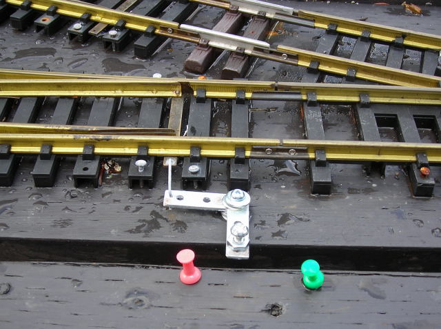
Pulling or pushing the choke cable moves a 90 degree angle bracket connected to the throw bar, which in turn moves the switch points. Plastic tubing has been added to the exterior of the choke cables to prevent rusting, and the cables can be lubricated by adding oil to the top under the handle.
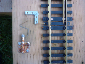
During the recent re-building of Nelson and Glen Hammond Yards, it was realized that moving the 90 degree angle brackets by hand could be used to throw the switches. This eliminated the need for the barrel bolts and V springs.
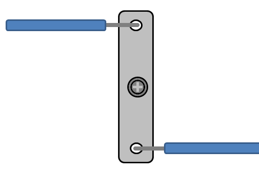
When a switch in a yard is out of reach, a choke cable is used to move the 90 degree angle bracket. The handle of the cable is mounted on the fascia of the yard deck nearby.
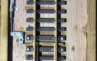
In an area such as the top of the wye in the Craig Leigh engine service facility, it may not be possible to reach a switch throw with one length of choke cable. In that instance, two chokes cables were joined together with small, metal bar.
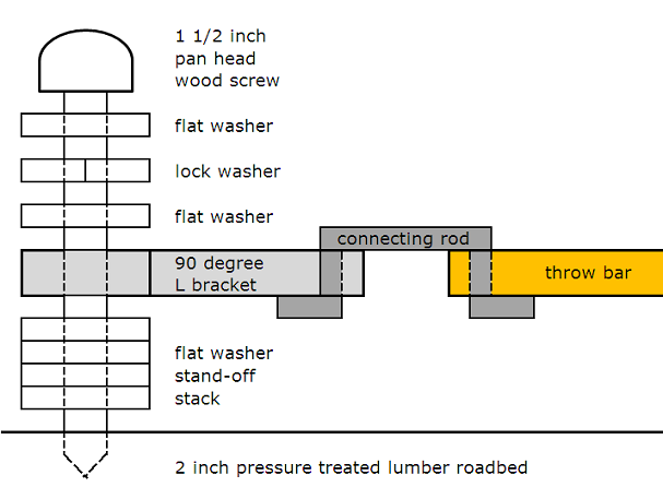
The following diagram details how the new 90 degree angle bracket switch throws have been mounted to the road bed.
The new throws proved to be very reliable during our railway operations over the past month, which included two days of continuous operations during the American Invasion of Ottawa. In time all the switches on the railway will be updated with the new throws.