
Although there is a comprehensive manual on the CD included with each throttle and receiver set, this article details how to quickly install and program the Revolution Train Engineer.
The information provided here was written in December 2008 before the Revolution Train Engineer was released for public sale. If it differs from the on-line Revised Manual available on the Aristo-Craft web site, the Revised Manual should take precedence. To read it, click on the link.
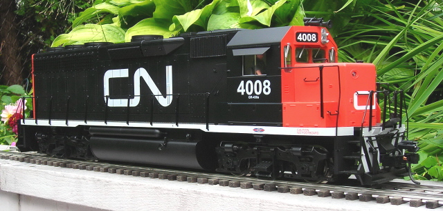
A GP-40 diesel will be used for this article, but the installation and programming should be similar for any Plug and Play locomotive.
REMOVING THE SHELL
Remove the handrails from the sides of the locomotive.
Place the locomotive upside down on a soft engine cradle taking care not to damage the horns.
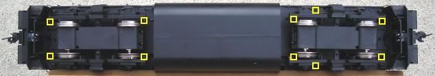
Remove the ten screws outlined in yellow that hold the shell to the frame.
- Two are at the very front behind the short hood pilot. Do not remove the screw in the center.
- Two are near the edge of the frame in front of the rear wheels of the front truck.
- Two are under the rear of the front truck.
- Two are just in front of the rear truck.
- Two are at the very rear behind the long hood pilot. Do not remove the screw in the center.
Turn the locomotive over and lift the shell from the frame from the back to the front. The long hood, cab and short hood will all come off as one piece. Set the shell on the engine cradle beside the frame taking care not to damage the horns. Fasten the ten screws back in the shell so they do not get lost.
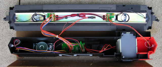
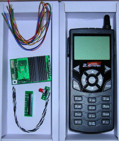
INSTALLING THE RECEIVER
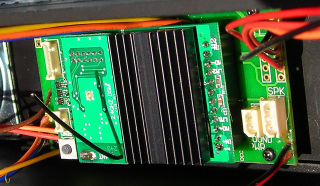
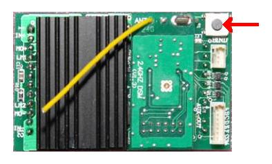
Remove the 12-pin DC plug from the front of the Plug and Play socket. Insert the Revolution receiver taking care to align the pins in the socket properly. Raise the antenna!
POWERING THE THROTTLE
On the back of the throttle is a slide cover. Slide the cover down and install three Alkaline AA cells. Close the cover.
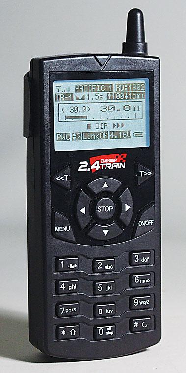
On the front of the throttle is an ON/OFF key. Hold the key down for a couple of seconds and the operating screen will light up.
QUICK PROGRAMMING THE LOCOMOTIVE RECEIVER
In order to link the throttle and receiver so they can exchange data to control the locomotive, a unique linking number and cab number must be assigned. These are similar to the frequency and channel numbers used by the 27 MHz and 75 MHz TE systems.
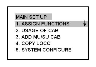
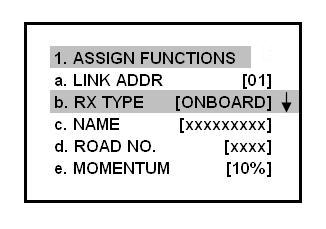
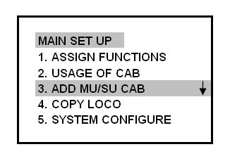
Press the MENU key. The MAIN SET UP menu will appear and item 1. ASSIGN FUNCTIONS will be highlighted. Push the STOP/ENTER key to select it.
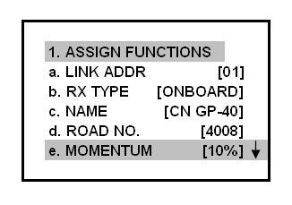
The ASSIGN FUNCTIONS menu will appear and item 1.a. LINK ADDR will be highlighted. The highest linking number 49 is displayed as the default. As this is the first locomotive to be programmed, linking number 01 will be selected by pushing the STOP key, and then the RIGHT ARROW key to display it. Future linking numbers between 02 and 49 can be selected by pushing either the LEFT OR RIGHT ARROW keys to move up or down numerically.
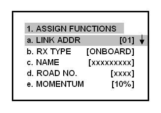
Push the DOWN ARROW key to highlight item 1.b. RX TYPE. As this is a locomotive, the ON BOARD default setting is applicable. NOTE: The LEFT ARROW key could be used to select BASE RX for a trackside Super Revolution receiver or other radio controlled accessories.
Push the DOWN ARROW key to highlight item 1.c. NAME. Use the alpha/numeric keypad to enter a name to identify the locomotive. The data is entered the same way as using a portable phone or cell phone. Road name CN GP-40 was used for this diesel.
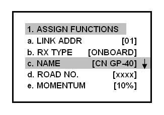
Push the DOWN ARROW key to highlight item 1.d. ROAD NO. Use the alpha/numeric keypad to enter a 4 digit road number. Road number 4008 was used for this diesel.
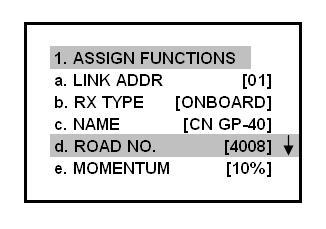
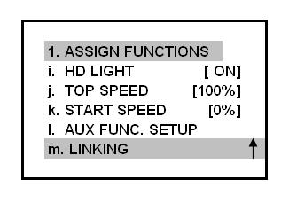
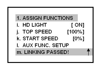
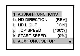
Items 1.e. to 1.l. are optional items. In order to operate and test the locomotive as soon as possible, these functions can be left in their default settings and set later any time the locomotive is stopped.
Press the DOWN ARROW key until item 1.m. LINKING is highlighted. Linking is similar to process used with the 27 and 75 MHz throttles and receivers.
The locomotive must be either track or battery powered in order for the receiver and throttle to be linked. An Aristo-Craft lithium-ion battery can be connected to the rear MU plug or the locomotive chassis can be set on a piece of test track with a maximum of 24 volts of power applied.
On the corner of the receiver, there is a small black momentary switch. Press and hold this button, indicated with the red arrow, until the small red LED on the receiver and the locomotive’s lights begin to flash. On the new Revolution receivers with sound, the remote linking button will have to be installed and used.
While the LED and lights are still flashing and item 1.m. LINKING is still highlighted on the throttle screen, press the STOP key to link the locomotive’s receiver and the throttle.
In a moment the screen will indicate LINKING PASSED and the red LED and locomotive’s lights will stop flashing.
ASSIGNING A CAB NUMBER
Press the MENU key. The MAIN SET UP menu will appear and item 1. ASSIGN FUNCTIONS will be highlighted
Push the DOWN ARROW key to scroll down to item 3. ADD MU/SU CAB. Press the STOP key to select it.
Just as each locomotive must have a unique linking number; it must also have a unique cab number. The highest cab number 49 is displayed as the default. As this is the first locomotive to be programmed, cab number 01 will be selected by pushing the STOP key, and then the RIGHT ARROW key to display it.
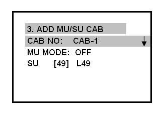
Push the DOWN ARROW key to scroll down to SU (Single Unit). It will have the default Single Unit linking number 49 displayed. Press the STOP and then the RIGHT ARROW key to display 01, the linking number previously assigned to this locomotive. The road name CN GP-40 will be displayed beside it.
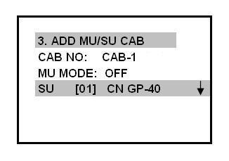
If another linking number had been assigned, pushing either the LEFT OR RIGHT ARROW keys to move up or down numerically, would display the number and road name.
TESTING THE RECEIVER
Press the MENU key twice to return to the OPERATING SCREEN. On the top of the screen it will show the locomotive’s road name (CN GP-40) and its road number (4008). In the second row it will show the cab number selected (Cab 1).
If you press and hold the UP ARROW key, the locomotive wheels would start to turn. Pressing the STOP key will stop the wheels.
Turn the power to the locomotive off. Press and hold the ON/OFF key for a couple of seconds to turn the throttle off for now.
INSTALLING THE SHELL
Remove the ten screws from the shell. Using the removal of the shell instructions as a guide, re-install the shell and the screws taking care not to pinch any wires between the shell and the frame or damage the horns. Re-install the hand railings.
OPERATING THE LOCOMOTIVE
If you are using track power, ensure the power switch on the locomotive is set to track power. Place the locomotive on the track and apply power. The lights may come on, but the locomotive should not move.
If you are using battery power, ensure the power switch on the locomotive is set to battery power. Place the locomotive on the track and plug a battery car into the rear MU plug. The lights may come on, but the locomotive should not move.
Press and hold the power ON/OFF key on the throttle for a second until the OPERATING SCREEN is displayed.
On the top of the screen there will be a name and road number of a locomotive. If it is not the locomotive under power, use the RIGHT or LEFT T keys to move up or down numerically, and display the correct name and road number of the locomotive.
To the left of the name is a series of four vertical bars indicating signal strength between the throttle and the locomotive’s receiver. On the bottom of the screen in the center there should be a Link OK indication, and to the right an indication of the throttle’s battery voltage.
Press and hold the UP ARROW key and the locomotive will begin to accelerate. In the center of the screen the locomotive’s speed and direction will be indicated. Press the DOWN ARROW key and the locomotive will decelerate.
When stopped, the LEFT or RIGHT ARROW keys can be pushed to change direction.
The STOP key can be used to immediately stop the locomotive.
Congratulations! You have installed your first 2.4 GHz Revolution Train Engineer.
OPTIONAL LOCOMOTIVE PROGRAMMING
As previously mentioned, there were a number of optional programming functions Items 1.e. to 1.l. that were left in default mode. These functions are used to change the running characteristics of a locomotive. They can be changed at any time the locomotive is at a full stop by using the ASSIGN FUNCTIONS menu. Any changes made will be effective as soon as the throttle is used. There is no need to re-link the locomotive.
If the throttle is not already on; press and hold the power ON/OFF key on the throttle for a second until the OPERATING SCREEN is displayed. Press the MENU key. The MAIN SET UP MENU will appear and item 1. ASSIGN FUNCTIONS will be highlighted. Push the STOP key to select it.
The ASSIGN FUNCTIONS menu will appear and item 1.a. LINK ADDR will be highlighted. Check to ensure the link address, road name and number are for the correct locomotive.
Press the UP and DOWN ARROW keys to highlight the desired functions. The Right and LEFT ARROW keys will let you change each highlighted function.
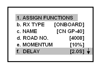
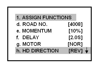
1.e – MOMENTUM: The rate at which the locomotive will accelerate or decelerate. Adjustable from 1% to 100% in 1% steps, the factory default is 10%.
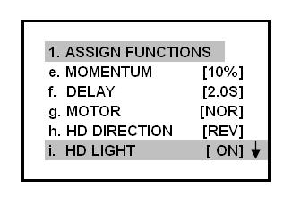
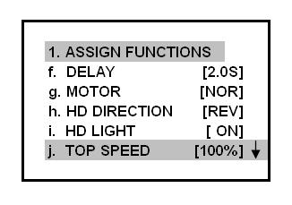
1.f – DELAY: The number of seconds a locomotive will pause while changing directions. Adjustable from 0 to 5 seconds in 1/10 of a second steps, the factory default is 1 second.
This is a personal favorite that I use during switching operations. The locomotive is slowed to switching speed and backed into a spur or siding to drop a car. By pushing the LEFT or RIGHT ARROW to change directions, the locomotive will slow to a stop (depending on the momentum setting), stop, pause for a couple of seconds (depending on the delay setting chosen) to allow the car to be uncoupled, and accelerate slowly in the opposite direction out of the spur or siding. I set the delay for 2 seconds which is time enough to uncouple Kadee couplers. With practice, this can also be used to pick up cars.
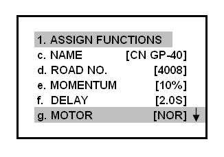
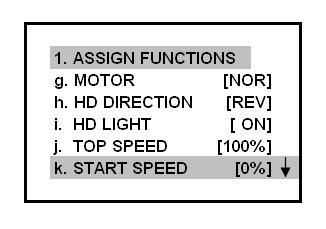
1.g – MOTOR: The direction the motors will normally turn. The factory default is NORMAL, the option REVERSE. This accomplishes the same thing as the NMRA/Large Scale switch in a Bachmann Annie, but with the push of a button. The OPERATING SCREEN has a graphic display showing the direction of travel.
1.h – HD DIR: This synchronizes the direction of the headlights with the direction of travel. The factory default is NORMAL, the option REVERSE. On one of my GP-40s I had to select reverse to have the lights function properly.
1.i – HD LIGHT: This turns the headlights on or off. If this locomotive were a trailing unit in a consist, the headlights could be turned off, but the cab light, number board lights, and porch lights would remain on even at a dead stop. NOTE: The change in headlight operation will not activate until the OPERATING SCREEN is displayed.
1.j – TOP SPEED: This sets the top speed as a percentage of its possible top speed. Adjustable from 1 % to 100% in 1% steps, the factory default is 100%. The top speed of the locomotive could be limited in case you were handing the throttle to an unsupervised child holding a cappuccino and a puppy. But it was more likely designed to adjust the top speed of dissimilar locomotives in a consist.
1.k – START SPEED: This adjusts the speed at which the locomotive will start to move. It is adjustable from 1% to 25% in 1% steps, the factory default is 0%. If a locomotive does not move until 12% power is applied, the start speed can be set to 12% and the locomotive will move with the first push of the UP ARROW key. This can also be used to adjust the start speeds of dissimilar locomotives that are run in a consist.
1.l – AUX FUNC. SETUP: This is used to choose between a momentary or latching function of keys 1 to 6 on the throttle. These keys can be used to activate the bell, or whistle, or horn of a sound board installed in the locomotive, or turn a smoke unit on and off. Latching leaves the accessory on until the button is pushed a second time for things like a bell or smoke unit. Momentary would sound a whistle or horn only as long as the button held down. The system includes a plug in cable for 6 different functions.
Push the STOP/ENTER key to select the AUXILLARY FUNCTION SETUP menu.
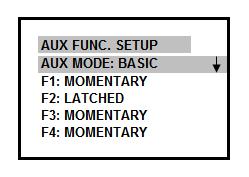
Use the DOWN and UP ARROW keys to select the function keys from 1 to 6, and the LEFT and RIGHT ARROW keys to change the function of the THROTTLE keys to latching or momentary operation.
Press the MENU key once to return to the ASSIGN FUNCTIONS MENU.
Press the MENU key twice and the OPERATING SCREEN will be is displayed.
ADDITIONAL LOCOMOTIVES
In time you may add 2.4 GHz TE receivers to other locomotives. As each locomotive requires a different cab number, you may have to change the default number of cab numbers allowed.
If the throttle is not already on; press and hold the power ON/OFF key on the throttle for a second until the OPERATING SCREEN is displayed. Press the MENU key. The MAIN SET UP MENU will appear and item 1. ASSIGN FUNCTIONS will be highlighted.
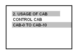
Press the DOWN ARROW key until item 2 USAGE OF CAB is highlighted.
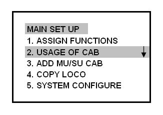
Push the STOP key to select it. The number of cab numbers currently available will be highlighted. Use the RIGHT ARROW key to increase the number from the default of 5 cab numbers. I chose 10 cab numbers; a cab number for each of my nine diesels and cab number zero to assemble a consist of locomotives.
Press the MENU key twice to return to the OPERATING SCREEN.
12 comments
Skip to comment form
Hello I have train revolution controller 2.4 and I just bought a protothrottle controller how can I use protothrottle on my DC system or how can I use the other controller it doesn’t seem to have input in or out just wireless
I’m afraid I don’t have an answer for you but you might be able to find someone who does by posting your question on one of the online forums such as https://largescalecentral.com
The link to the revised manual is no good, would be a good idea to point to the new site for the manuals.
hi iam peter I have 5 engines set up good on the hand control I want to use 2 hand set but I am having trouble setting the same engines into this hand set please could you help
If you want to add the same locomotives to two throttles (hand held transmitter).
They both have to be set to the same RF-CHANNEL and GROUP ID numbers.
In the operating screen of the first throttle, press the MENU key.
In the MAIN SET UP menu, use the DOWN ARROW key to scroll down to Item 6 RADIO CONFIGURE.
Press the STOP/ENTER key.
Make note of the RF-CHANNEL and GROUP ID numbers.
Press the MENU key twice to return to the operating screen.
In the operating screen of the second throttle, press the MENU key.
In the MAIN SET UP menu, use the DOWN ARROW key to scroll down to Item 6 RADIO CONFIGURE.
Press the STOP/ENTER key.
Change the RF-CHANNEL number to match the first throttle by using the RIGHT or LEFT ARROW keys.
Change the GROUP ID number to match the first throttle by using the RIGHT or LEFT ARROW keys.
Press the MENU key twice to return to the operating screen.
As of 1 January 2017, there is now a new company, Precision RC, that is now making the Revolution products.
Here is the link for their web site.
https://www.revoelectronics.com/
Hi Paul, I have the 2.4 Crest T.E. I have 15 Rx numbered for Cabs 0 to 14. I have no problem in SU operation, but do not know how to set the cab number for the consists once i make up the consists and my Tx shows each as MU. I plan on keeping about 6 MU sets permanently, but don’t know the steps. Everything else is clear to me. Also if example I have an A unit, can I copy the address to run them together as MU? I would like to set the cab numbers from 39 to 49 in case I acquire more motive power.
Thanks in advance for any info.
Sonny
If in the operating screen, press the MENU key.
In the MAIN SET UP menu, select item 3. ADD MU/SU CAB.
The cab number should be shown on the first line.
If not use the right or left arrow to select it.
Scroll down to the next line.
It should read MU MODE: OFF.
Use the RIGHT arrow key to select MU MODE: ON
Press the MENU key to return to the operating screen.
Repeat this for the next locomotive.
The LEFT arrow key will turn the MU MODE: OFF when needed.
If you are using two like locomotives, like an FA-1 FB-1 set.
Individually set each of them the same cab and linking numbers, and link it.
They will now respond equally as a pair.
If the locomotives are not alike, there speed adjustments that can be made in the ASSIGN FUNCTIONS menu.
START SPEED, STOP SPEED and SPEED CURVE.
The Revolution throttle Emergency Stop button scrolls through the cab numbers started at the bottom.
If you use the top numbers, those locomotive may take a while to stop in an emergency situation.
As of 1 January 2017, there is now a new company, Precision RC, that is now making the Revolution products.
Here is the link for their web site.
https://www.revoelectronics.com/
Hi Paul
Thanks for the quick response !
Yeah that long-winded nebula url /link is the one found on the Crest support page.
Looking thru it, definitely the manual is previous to the sound receivers rollout.
later,
doug c
Darn the revised manual link does not connect anymore to the proper page due the major changes done to their website.
hmmm, would this link to the Crest supportpage>revo manual be THE (or a newer) revised manual;
http://nebula.wsimg.com/21615d66c4b6b4892c80fc2954e4d51e?AccessKeyId=9C5095D46D9806926E59&disposition=0&alloworigin=1
Thanks for all the information you put together for all of us out here !
doug c
p.s. i finally purchased the cre57000SD set and another decoder on Wed. from UT. Hope to test both decoders on a loco within a couple days.
Hi Doug!
Here is the link to Crest Support for the Revolution Manuals
http://www.crest-electronics.net/support.html
Wondering if you could help me.I have a bachmann spectrum 4-4-0 american and was wanting to install the revolution in it but with track power.Any help would be greatly appreciated..Thanks Jimmy.
Hi Jimmy!
The Revolution receiver could be installed in the tender and powered from the track pick-up wires mounted on the posts there.
A 2-wire connector (MU Plug) from output (MOTOR) wires from the Revolution receiver could be connected directly to the motor in the locomotive. Any other wires to the motor, like those from the locomotive’s track power pickups or power switch would have to be unsoldered.