
Sound really adds an extra level of realism and enjoyment to any locomotive. This article shows a number of methods of wiring a Phoenix Sound P8 to a Revolution receiver. The wiring suggestions explained are just a general guide. For detailed instructions on how to install a sound board in a specific locomotive, refer to this Sound Installation Section .
TRIGGER WIRES
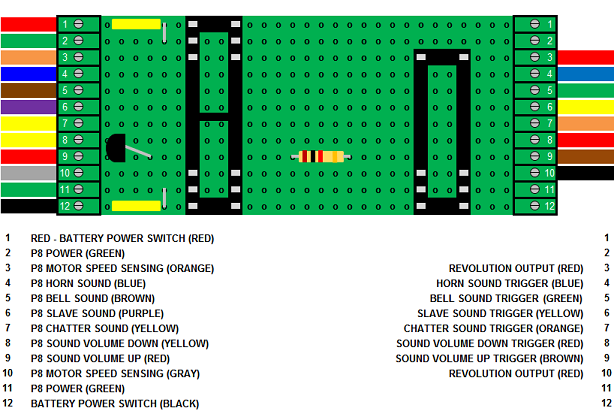
When installing a P8, there are 6 trigger wires on the sound board and 6 trigger wires on the Revolution receiver to connect together. Unfortunately the wire colours do not match, so a chart like this one for diesels helps keep things straight.
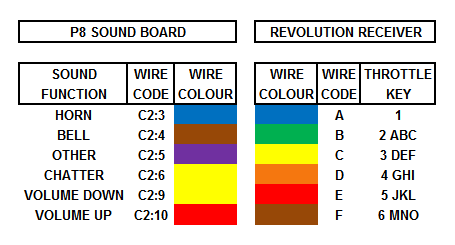
Although the wire colours do not match, the wire codes for the P8 and receiver are in ascending order, as are the throttle key designations.
Note the reference to “Other” in the diesel sounds chart for the P8. Although the manual shows this as “Slave”, neither of the two boards I have installed so far have that sound. One has an “All Aboard” announcement, the other a “Dynamic Brake” whine. These sound functions can be changed with the Phoenix Sound Computer Interface accessory, but I have yet to find the printed information on how that is done.
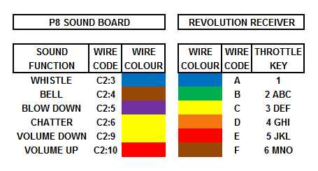
The steam sounds chart is similar, except the “Whistle” and “Blow Down” sounds replace the “Horn” and “Other” sound functions.
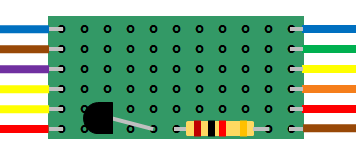
Although it is possible to solder and shrink wrap all these wires together, I prefer to use a circuit board with screw terminals to connect them. The reason becomes clear as you read on.
The trigger wires discussed in this section are found on two connectors. The C2 connector for the P8 and the auxiliary control harness connector for the receiver. These two connectors have some wires which will not be used in most installations, and have not been shown or mentioned for that reason. The exception are the blue and orange wires (C2:1 and C2:2) on the P8 which is used to connect the reed switch supplied by Phoenix Sound to trigger the steam chuff sound.
STEAM CHUFF SOUND
The black wires of the reed switch supplied by Phoenix Sound for steam locomotives are soldered and shrink wrapped to the P8 blue and orange trigger wires (C2:1 and C2:2). The magnets supplied are fastened on one the locomotive or tender wheels and the reed switch is mounted 90 degrees to them. When a magnet passes the reed switch, it closes and triggers the steam chuff sound.
SOUND VOLUME CONTROL
The Phoenix Sound P8 comes with a momentary switch to raise and lower the sound volume. But hiding the switch so it does not alter the appearance the locomotive does not allow it to be accessed while operating. Fortunately Phoenix Sound has posted a diagram of a small circuit that can replace the switch and allow the volume to be raised and lowered with two trigger keys on the throttle.
The circuit uses a 1K ohm resistor and a 2N3906 transistor which can be mounted on a small piece of perf board between the P8 and receiver.
The resistor, transistor, and perf board can all be purchased from All Electronics under catalog numbers 293-1K, 2N3906 and ECS-4. OVGRS members can purchase the electronic components required by contacting Paul Norton.
The 2N3906 transistor has three leads: the collector, base and emitter. Relax! That’s all you have to known about this device.
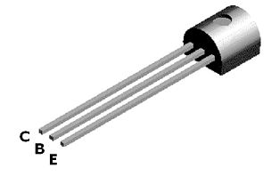
To assemble the volume control circuit, leggings will be added to the collector and emitter leads of the transistor. These leggings will be colour matched to the P8 yellow and the red triggers wires (C2:9 and C2:10) for the sound volume control functions. They will also set the transistor at the right height above the perf board for soldering and ensure they do not touch the center lead (base) when it is bent to fit.
Remove an inch of insulation off some yellow 22 gauge wire and cut a piece exactly 3/16ths of an inch long from it. Slip the piece over the left lead (collector) and push it flush against the bottom of the transistor.
Remove an inch of insulation off some red 22 gauge wire and cut a piece exactly 3/16ths of an inch long from it. Slip the piece over the right lead (emitter) and push it flush against the bottom of the transistor.
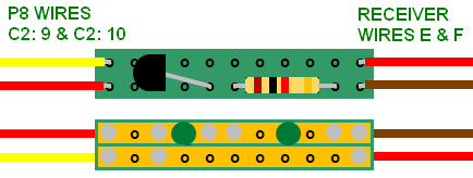
Bend the center lead (base) straight out at the top from the flat side of the transistor. With the round side of the transistor facing the left edge of the component side of the perf board, fit the two outside leads (collector and emitter) in the third row of holes. Bend the bottom of the center lead (base) until the end fits in the fifth hole in the bottom trace as shown.
Glue the bottom of the leggings to the perf board with CA (super glue) so the transistor will not fall out when the board is flipped over for soldering.
Flip the perf board over. Flux and solder all three leads in place, and trim the excess from them. Break open the trace between the emitter and base leads, as indicated with the big green dot, using a 1/8 inch drill bit in a pin vise.
Bend the leads of a 1K ohm resistor so they will fit in the bottom trace on the component side of the perf board as shown. Flip the perf board over. Flux and solder the leads in place, and trim the excess from them. Break open trace between the leads, as indicated with the big green dot, using a 1/8 inch drill bit in a pin vise.
Solder the yellow and the red triggers wires (C2:9 and C2:10) from the P8 to the left hand side of the perf board as shown.
Solder the red and the brown trigger wires (E and F) from the receiver to the right side of the board. That allows throttle key 5 jkL (L for Less) and throttle key 6 Mno (M for more) to lower and raise the volume.
INTERFACE CIRCUIT BOARDS
In the previous section a small circuit board was assembled to connect the trigger wires to raise and lower the sound volume using two throttle keys. But that still leaves 4 more P8 triggers wires and 4 more receiver wires to connect. A simple solution would be to assemble a wider interface circuit board so that all 12 trigger wires could be fastened together.
Taking it one step farther, a longer piece of perf board could be used and screw terminals added so the trigger wires could be connected together without soldering and shrink wrapping them all.
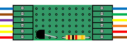
The terminal blocks are manufactured by Phoenix Contact and are available from Mouser Electronics under the manufacturer’s part number 1725698 for the 6-position version.
P8 POWER
The P8 connector C1 has 6 coloured wires: 2 green to power the sound board, two brown to power the speaker, and a set of orange and gray wires to measure the motor voltage.
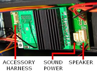
In some locomotives there are headers or solder pads to connect the P8 green power wires (C2:1 and C2:2). However care must be taken to ensure these wires are connected to the battery or full track power source like the receiver. In some locomotives the headers and solder pads are labeled “SOUND PWR”, but are actually connected to the receiver’s output (motor) wires. As the P8 does not have a small battery attached to power it when the locomotive is stopped, the sound functions would stop as well.
A voltage meter can be used to test the header or solder pads to see if the voltage displayed is the same as the power source when the locomotive is stopped. If it does, a small battery connector can be soldered and shrink wrapped to the P8 green power wires (C2:1 and C2:2) and they can be plugged into the header.
The small battery connector can all be purchased from All Electronics under catalog number SMB-2. OVGRS members can purchase the connector by contacting Paul Norton.
If the voltage rises as the locomotive accelerates and decelerates, the header or solders pads are connected to the receiver’s output (motor) leads and should be used to connect the P8 orange and gray motor voltage measuring wires (C2:1 and C2:2). That is covered is described in one of the following sections.
In non Plug and Play locomotives, the P8 green power wires can be soldered to the input wires of the receiver labeled “TRK” on an adapter board, or under the screw terminals on a Plug and Play Board labeled “TRK”. On the newer adapter and Plug and Play boards, the screw terminals are labeled “INPUT”.
SPEAKER WIRES
The set of brown wires (C2:3 and C2:5) on the P8 are used to connect the sound board to the speaker. If the speaker came with the sound board and there is not one in the locomotive, the installation is simple. When the speaker is installed in a suitable location, the white connector on the P8 brown wires is plugged into the white connector on the speaker’s brown wires.
Some Plug and Play locomotives already have a speaker installed, and a header on the Plug and Play socket labeled “SPEAKER”. The white connector on the P8 brown wires (C2:3 and C2:5) plugs into the header to connect the speaker to the sound board.
Others have a speaker installed and solder pads to connect the P8 brown wires (C2:3 and C2:5).
P8 MOTOR VOLTAGE READING
The set of orange and gray wires (C2:6 and C2:7) on the P8 are used to measure the motor(s) voltage. By doing this the sound board can alter the diesel prime mover sound or steam chuff sound to match the speed changes of the locomotive. But like the power wires, some locomotives have headers or solder pads to connect these wires, and some do not.
In some Plug and Play locomotives there are headers labeled “SOUND PWR” to connect the P8 orange and gray motor voltage measuring wires (C2:6 and C2:7). However care must be taken to ensure these wires are connected receiver’s output (motor) wires and not to the battery or full track power source for the receiver.
A voltage meter can be used to test the header to see if the voltage displayed rises and falls as the locomotive accelerates and decelerates. If it does, the header is connected to the receiver’s output (motor) leads. A small battery connector can be soldered and shrink wrapped to the P8 orange and gray wires (C2:6 and C2:7) and plugged into the header.
The small battery connector can all be purchased from All Electronics under catalog number SMB-2. OVGRS members can purchase the connector by contacting Paul Norton.
If the voltage displayed is the same as the power source and remains constant, this header is to be used to connect the green power wires (C2:1 and C2:2) for the P8.
In non Plug and Play locomotives, the P8 orange and gray motor voltage measuring wires (C2:6 and C2:7) can be soldered to the output wires of the receiver labeled “MOTOR” on an adapter board, or under the screw terminals on a Plug and Play Board or newer adapter board labeled “MOTOR”.
PROGRAMMING JACK CONNECTOR
The remaining connector C3 is used to connect the programming jack for the Phoenix Sound Computer Interface to the P8.
This accessory is used to customize sound files or upload upgraded ones. Every sound function including the steam chuff can be modified to suit the locomotive owner’s personal preferences.
SUPER SOCKETS
To install a Phoenix Sound P8 in a radio controlled Plug and Play locomotive requires connecting: 2 power wires, 2 speaker wires, 2 motor voltage measuring wires, and 12 to 14 trigger wires. Some of the wires may have headers or solder pads to connect to, and the remaining wires could be connected using the small interface circuit boards previously mentioned. But installing a P8 in a non Play and Play locomotive requires connecting all 18 to 20 wires.
A combination of an adapter or Plug and Play Board with screw terminals and a small interface circuit board could handle all the wiring. But the adapter or Plug and Play Board would have as many as: two motor wires and a motor voltage measuring wire under each “MOTOR” screw terminal, a P8 power wire and a track or battery power wire under each “INPUT” screw terminal, and two wires to power the front and rear lights under screw terminal “COM”. The result is an ugly and confusing spaghetti bowl of wiring which is not only difficult to wire, it is almost impossible to trouble shoot.
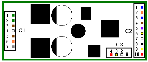
To solve the problem, Super Sockets with screw terminals at both ends can be assembled. Below is a diagram of one that was recently used to convert a USA Trains SD-70 to battery power, radio control, and sound.
A Super Socket is easy to assemble. The terminal blocks on the ends provide an individual screw terminal for each of the wires which make it easy to wire and trouble shoot. Additional components such as the transistor and resistor for sound volume control, IC sockets to plug the receiver into, and polyfuses to protect the P8 and receiver are mounted on the circuit board.
For detailed information on how to assemble a Super Socket, just read the articles on installing a P8 sound board in the Sound Installation Section.
2 comments
I’m a newbee and wanted to start out with battery power and sound. I’m a EE so the electronics is not an issue. However, most everything else is new to me. I just received my first locomotive yesterday and was totally perplexed just trying to figure out how to open it up. Your instructions and illustrations are remarkable! Thank you so much.
I’m a member of the Gateway Garden Club in St. Louis. I dabble in installing batteries and sound in my engines. When i run across some installation problems, I use take quite a while to figure things out. I still have to trouble shoot a lot. I’m currently installing revolution and P8 sound in USA NW2 cow and calf with a battery car for another member in the club. I decided to see if there was any information on the internet and discovered your web site. You can bet I bookmarked this site. Not only do you have an enormous amount of information, but it is really presented well. Thanks!!i
Incidentally, I grew up in Tupper Lake, NY on the other end of the New York and Ottawa Railroad, although it was history by the time I grew up.
Bob