
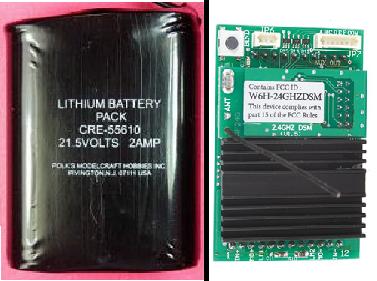
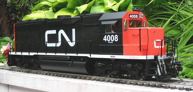
This article details the conversion of an Aristo-Craft GP-40 diesel from track power to on-board, battery power and radio control using an Aristo-Craft lithium-ion battery pack and Revolution receiver.
The article appears long because it is detailed and includes lots of pictures. But if you take your time and follow it step-by-step it is not difficult, and the results are well worthwhile. Although a GP-40 was used for this installation, the instructions could be used as a guide to re-power other Aristo-Craft Plug and Play diesels.
Nothing prevents the locomotive from being restored to its original condition for re-sale at a later date, as anything removed from the locomotive will be stored intact in a small Ziploc bag.
Please read this article carefully, highlighting the components that are needed. Sources of supply are suggested for items not sold by your hobby suppliers. OVGRS members can purchase the required components by contacting Paul Norton.
REMOVING THE SHELL
Remove the cover for the switches from the top of the locomotive.
Remove the handrails from the sides and ends of the locomotive.
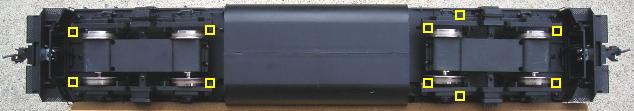
Place the locomotive upside down on a soft engine cradle taking care not to damage the horns.
- Remove the ten screws outlined in yellow that hold the shell to the frame, and place them in a small container so they do not get lost.
- Two are at the very front behind the short hood pilot. Do not remove the screw in the center.
- Two are near the edge of the frame in front of the rear wheels of the front truck.
- Two are under the rear of the front truck.
- Two are just in front of the rear truck.
- Two are at the very rear behind the long hood pilot. Do not remove the screw in the center.
Turn the locomotive over and set it on its wheels. Lift the shell from the frame from the back to the front. The long hood, cab and short hood will all come off as one piece. Set the shell on the engine cradle beside the frame taking care not to damage the horns.
Fasten the 10 screws in the small container back in the shell.
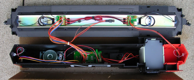
Remove the white tie from the wiring.
Unplug the 3 and 6-wire connectors from (Printed Circuit Board) PCB04 on the frame under the long hood. The 3-wire connector is for the rear lights.
Unplug the 3-wire connector for the front lights from PCB05 on the frame near the cab.
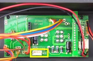
Unplug the connector from the 3-pin header on the Plug and Play PCB01 in the shell. This header is for the voltage regulator and is labeled “REG” on the PCB.
Set the shell aside for now.
DISCONNECTING THE TRACK POWER PICK-UPS
It is imperative that the track power pick-ups be disconnected so the locomotive can never pick up track power or feed battery power into the tracks. The result could be electronically catastrophic.
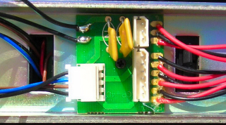
Unplug the 4-wire connectors from PCB04 and PCB05 on the frame. Remove the two black wires from each connector by pressing down on the small metal tabs and gently pulling on the wires.
Shrink wrap the terminals on each of the four black wires, and tape them to the frame out of the way.
REMOVING THE MU CONNECTORS
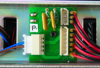
Aristo-Craft Plug and Play diesels have MU connectors at each end that are attached to the internal power buss of the locomotive. As the locomotive will be powered with an on-board battery pack, the MU connectors are redundant. One of the wires of each MU connector on the PCB04 and PCB05 is marked with white paint. Mark the solder pad on each PCB to which it is attached. Unsolder all four MU connector wires.
Remove the hot glue holding the MU connectors to the frame and remove them. Place the connectors in a small Ziploc bag labeled GP-40, as well as, the road name and number of the diesel.
WIRING THE BATTERY PACK SWITCH
As the battery pack will be charged on-board, a double-pole double-throw (DPDT) center-off switch is needed to toggle the battery pack between its charging connector and the internal power buss of the locomotive. In run mode the receiver will be battery powered through the internal power buss, and will power and control the motors and lights.
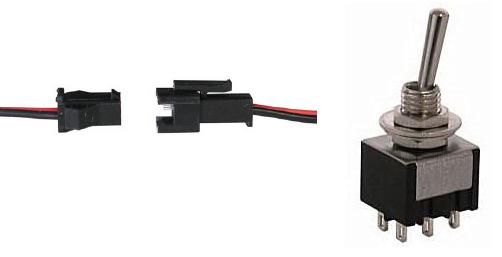
Two connector sets will be used to connect the battery pack switch to the battery pack, charger, and power buss of the locomotive. The connector sets and switch are both available from All Electronics under catalog numbers CON-240 and MTS-12 respectively. OVGRS members can purchase the connector sets and switch by contacting Paul Norton.
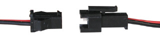
The wires on the connector sets sold by All Electronics may not be positioned the same as the wires on the connectors of lithium-ion batteries and chargers. If not, click on the following link to see how to switch the positions of the AE Connector Set Wiring so that proper polarity is maintained.
The male half of an All Electronics connector set will be used to connect the lithium-ion battery pack to the center terminals of the battery pack switch. The male connector shown on the right is the same as the one on an Aristo-Craft lithium-ion battery pack charger. As it is easier to solder and shrink wrap the wires to the terminals of the switch before it is installed; place the switch in a small bench vise with the terminals facing up.
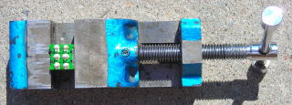
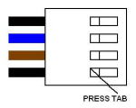
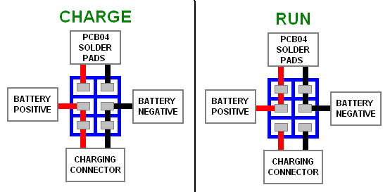
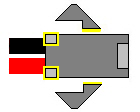
Solder and shrink wrap the wires of the male connector to the center terminals of the switch as shown in the following diagram.
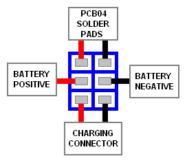
The female half of the connector set shown on the left will be used as the battery charging connector. It has the same connector as an Aristo-Craft lithium-ion battery pack.
Cut the wires of the connector set to 4 inches in length. Solder and shrink wrap them to the bottom terminals of the switch as shown in the diagram below.
The second connector set will be used to connect the battery pack switch to the power buss of the locomotive. Solder and shrink wrap the wire of the female connector to the top terminals of the switch as shown in the diagram above. Check to ensure all the wires on one side of the switch are red, and the other side black.
Disconnect the male half of the connector set. Solder the end of the red wire to the solder pad which was marked on PCB04 on the rear of the frame when the MU plug was removed. Solder the black wire to the other solder pad.
That completes the wiring of the battery pack switch. It will be mounted on a styrene platform under the switch cover.
BATTERY PACK SWITCH PLATFORM
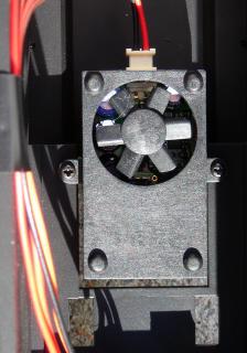
The battery pack switch, charging connector, and remote linking button for the receiver will be installed on a styrene platform in place of the smoke unit. This will allow them to be accessed easily by removing the switch cover from the top of the long hood. Replacing the cover hides the components and protects them from the elements.
Turn the shell over and remove the white connector from the front of the smoke unit. Undo the two small screws and remove the smoke unit. Place the two screws in a small container so they do not get lost. Place the smoke unit in the small Ziploc bag with the MU plugs.
From a 1/16th inch thick styrene sheet, cut two pieces 1 15/16 inches wide by 1 1/2 inches tall.
From each of the top corners of one of the pieces measure 1/4 inch down and 1/4 inch in, and place a mark.
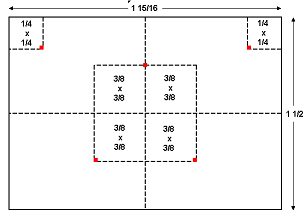
Draw a horizontal and a vertical line that will divide the whole piece into equal quarters. Draw lines 3/8ths of an inch above and below the horizontal center line, and 3/8ths of an inch to the left and right of the vertical center line to form the box shown in the diagram above. Place a mark in the center of the top line of the box. Place a mark at each of the outside corners on the bottom line of the box.
Tape the two pieces together. At each of the marks at the top of the marked piece, drill a hole with a 1/8th inch bit through both sheets. Remove the tape and enlarge the holes in the marked sheet with a 1/4 inch drill bit. Glue the sheets together making sure the edges are all flush and the larger holes are centered over the smaller ones. When the glue is dry, test the platform to ensure it fits over the nubs and flush against the hood.
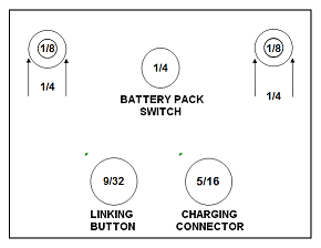
At the mark in center of the top line of the box, drill a hole with a 1/4 inch drill bit for the battery pack switch.
At the mark in the bottom left hand corner of the box, drill a hole with a 9/32nd inch drill bit for the remote linking button.
At the mark in the bottom right hand corner of the box, drill a hole with a 5/16ths inch drill bit for the charging connector.
That completes the assembly of the components platform.
INSTALLING THE BATTERY PACK SWITCH
Mount the battery pack switch in the 1/4 inch hole in the top of the platform so it toggles from side to side. When looking at the bottom of the platform, the wires for the charging connector should be on the right of the switch, and the wires for the power buss on the left.
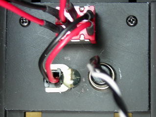
Remove the black shell from charging connector wires using the instruction in the AE Connector Set Wiring fix.
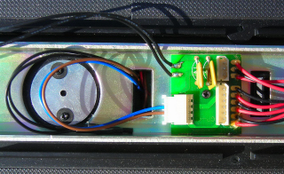
Spread the wings of the shell out 90 degrees and wiggle the base through the 5/16th inch hole on the bottom right of the platform. The locking nub on the connector should face the cab of the locomotive. On the underside of the platform, slide a 1/4 inch spade terminal under the tabs on the base to hold it. You may have to remove the shaft of the spade connector to get the remote linking button to fit. Secure it with hot glue as shown in the picture above.
CAUTION: It is imperative that the polarity of the charging connector wires is correct, or the battery charger will drain the lithium-ion pack to a point beyond repair. Using the connector on the battery pack as a guide, install the red and black wires in the charging connector. If you have a lighted magnifier, there are small numbers on the very bottom of the connector where the wires are inserted. The red wire should be in position 1 for an Aristo-Craft lithium-ion battery pack.
Mount the remote linking button in the 9/32nd inch hole on the bottom left of the platform.
Install the switch platform using the two screws from the smoke unit in the small container.
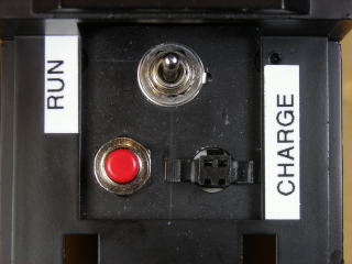
Place a “RUN” label to the right of the switch and a “CHARGE” label to left to indicate which way the switch should be toggled. Right now make sure it is in its center-off position.
That completes the installation of the battery pack switch, charging connector, and remote linking button. The battery pack will be connected when it is installed, and the linking button when the receiver is installed. The power buss connectors will be joined when the locomotive is re-assembled.
CHARGING THE BATTERY PACK
If the battery pack has not been charged, use an Aristo-Craft, lithium-ion battery pack charger to top it up. If you have the old style charger without the full charge indicator, test the battery pack once an hour. Connect the male half of a connector set to it, and use a voltage meter across the free end of the wires to take a reading. A fully charged Aristo-Craft lithium-ion battery pack should read 25.2 volts, and should not require any more than 4 hours on the charger.
INSTALLING THE BATTERY PACK
Set the frame on its side on a soft surface. There is a tab at each end of the fuel tank that holds it to the frame. Push the tabs toward the center of the tank and gently pull to remove the tank.
Undo the nut and bolt that holds the rear weight to the frame and remove them. The battery pack will be mounted in its place. Place the weight, bolt, washer and nut in a separate Ziploc bag. Label the bag with GP-40, as well as, the road name and number.
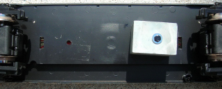
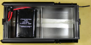
Remove enough hot glue from inside the rear of the fuel tank between the air tanks so the battery pack can sit flat. Place Velcro dots on the bottom of the battery pack and fasten it to the bottom of the fuel tank.
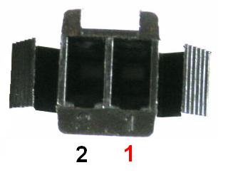
Remove the wings from the sides and the two small nubs outlined in yellow from the bottom of the connector on the battery pack wires.
The hole left in the frame by the screw that held the rear weight must be enlarged to let the battery pack connector pass through it. To ensure that none of the 9 wires are damaged, drill from the top of the frame with a 5/16ths inch drill bit. Chamfer the edges of both ends of the hole so the battery pack wiring does not get chaffed.
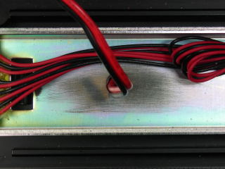
Pass the battery pack connector through the hole in the frame, and remove any excess slack in the wiring. Install the fuel tank.
That completes the installation of the lithium-ion battery pack. It will be connected when the locomotive is re-assembled.
INSTALLING THE RECEIVER
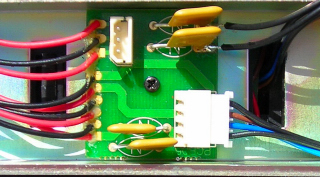
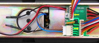
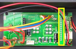
Place the shell upside-down of a soft surface, and set the frame beside it. Plug the 3-wire connector for the voltage regulator into the 3-pin header outlined in yellow and labeled REG on the Plug and Play PCB01.
Remove the 12-pin DC plug outlined in yellow from the front of the Plug and Play socket.
Install the Revolution receiver, ensuring the pins on both ends are properly lined up with the Plug and Play socket. Straighten the antenna.
Plug the remote linking button connector into the 2-pin header on the back of the receiver.
That completes the installation of the receiver and the remote linking button.
PROGRAMMING AND TESTING THE RECEIVER
Make sure the battery pack switch is in its center-off position. Check to ensure the wire colours of the battery pack connector and the connector soldered to the center of the battery pack switch match. Plug the two connectors together.
Plug the connector soldered to PCB04 on the rear of the frame, into the remaining connector soldered to the battery pack switch.
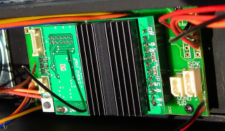
Plug the 6-wire and 3-wire connectors indicated with the yellow arrows into PCB04.
Plug the 3-wire connector for the front lights into PCB05 on the frame near the cab.
Remove the ten screws from the shell, and place them in a small container. Gather the wiring together and secure it with the white twist-tie or a small cable tie. Set the shell on the frame taking care not to pinch any wiring.
The information on how to program the receiver is in the Installation and Operation Manual for the Revolution Train Engineer that is on the CD that comes with the set. The Installation and Operation Manual for the Revolution Train Engineer is also available on the Aristo-Craft web site as an Adobe pdf file. To read or download the manual, click on the link.
Carefully place the locomotive on a test stand or rollers so the wheels can turn freely. Toggle the battery switch to the run position, and program the receiver.
Test to ensure the motors and lights respond properly to the throttle, and that the lights and motor direction are in synch. After testing, return the battery pack switch to its center off position.
INSTALLING THE SHELL
Place the locomotive upside down on a soft engine cradle taking care not to damage the horns.
Fasten the shell to the frame using the 10 screws in the small container.
Place the locomotive on its wheels. Re-install the handrails to the sides and ends of the locomotive.
To make the switch cover easier to remove to access the battery switch, charging plug, and linking button, the metal tabs that hold it to the hood can be removed. This will also prevent anyone from trying to pick up the locomotive by the switch cover, and having it fall when the metal tabs let go.
Remove the four screws from the bottom of the switch cover. Place the metal tabs in the Ziploc bag with the smoke unit. Fasten the four small screws back in the cover so they do not get lost. Place the cover for the switches back on top of the locomotive.
CONGRATULATIONS! You have successfully converted an Aristo-Craft GP-40 to on-board, battery power and radio control.
ENJOY!
3 comments
Very interesting article. I have just obtained an Aristo Craft SD-45 that has an internal battery installed and the toggle switch is labeled “T” (switch to the left ) and “L” (witch to the right) with center position not marked which I assume is neutral. I am puzzled over what the “T” and “L” represent? I am a newbie to battery power. Any help would be appreciated.
Hi Carl!
Unfortunately I don’t know what those markings represent.
If there is an internal battery, there is probably a Radio Control receiver installed as well. Did you get a throttle to operate this locomotive when you bought it? If not, open the locomotive and check to see if there is a receiver in the Plug and Play socket.
Most Double Pole – Double Throw – Center Off switches in my installations do the following:
Throwing the switch one way will connect the battery to a Radio Control receiver in the Plug and Play socket to power and control the locomotive. The lights should come on and the locomotive move when the throttle is used, if the battery is charged.
Throwing the switch the other way will isolate the receiver from the battery, and connect the battery to a battery charging plug or jack. Testing the jack or plug with a volt meter should give you a voltage reading of the battery and let you know if it is charged or not.
The center position should be the off position for both locomotive power and the battery charging plug. The locomotive should not move when the throttle is used, and the battery charging plug should not provide a voltage reading.
Thanks much for this article, Paul.. I have been trying to mod an Aristo SD45 withoutr success, but I think this article has “shown me the light” 4/4/14