
This article shows how to add an MU connector to the rear of a USA Trains F-3A so you can use a trailing power and control car to run it.
As the locomotive’s track power wiring will be unplugged during this project, a power and control car will be required to run it. A power and control car is simply a battery car with a receiver added for on-board, radio control. To view an article on how to build a Power and Control Car, just click on the link.
Nothing in this project prevents this locomotive from being restored to original condition for re-sale at a later date.
While this project deals with a specific locomotive, the principles are the same for other USA Trains four axle diesels.
REMOVING THE TRACK POWER SLIDERS
Place the locomotive upside down in a soft cradle taking care not to damage the horns. Place a piece of foam or pieces of cardboard between the top of the motor blocks and the frame. This prevents the motors blocks from dropping and dislodging the axles when the bottom covers are removed. Remove the six screws (circled in red) from the bottom of each motor block and remove the bottom covers.
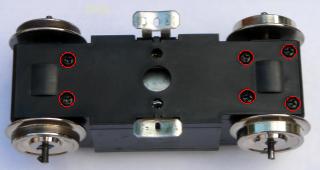
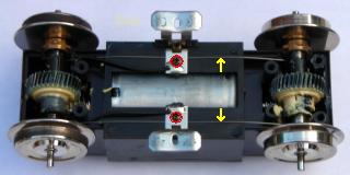
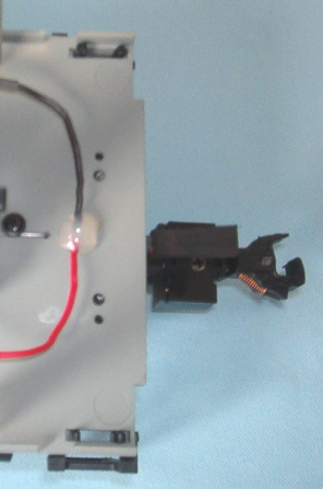
Remove the small screw (circled in red) from each track slider bracket. Lift out the track sliders and the wire axle track power wipers (indicated with yellow arrows) sprung between the axles.
The track sliders and axle wipers are the only components removed during this project. Place them in a Ziploc bag labeled with F-3A, as well as, the road name and number. Tape it in a pocket of the locomotive’s Styrofoam packaging so parts do not get lost.
Fasten the track slider brackets back in place. Fasten the covers back on the bottom of the motor blocks. Remove the foam or cardboard from under the motor blocks.
REMOVING THE F-3A SHELL
Remove the two screws from the base of the coupler mounting brackets and remove the couplers. Fasten the screws back in the frame so they do not get lost or mixed up with others.
Undo the two screws at the base of the fuel tank. Lift the fuel tank off and fasten the screws back in the frame so they do not get lost or mixed up with others. Place the couplers in the fuel tank and set them aside for now.
There are nine screws holding the shell to the frame. These are hidden in deep burrows in the frame and will require a long Phillips #1 screwdriver to remove them. It is not necessary to remove the motor blocks in order to access these screws; however the first screw hidden under the front motor block is difficult to get at.
Remove the leaf spring stirrup and side frame from the front motor block. Place the three screws in the small container so they do not get lost.
Slip the front axle from its remaining side frame, and flip the motor block towards the center of the locomotive. Remove the first screw from its burrow.
Flip the motor block back, and slip the axle back in the side frame. Fasten the other side frame back on using the three screws in the small container. Install the leaf spring stirrup.
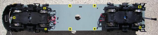
- The next two screws are under the side frames at the back of the front truck.
- Four are in the fuel tank area.
- The last two are under the side frames at the back of the rear truck.
Place a forefinger in the hole in the center of the frame and GENTLY pull down. The frame should bow SLIGHTLY. Push down on the front pilot anti-climber and the front of the shell should pop free of the frame. Pull the frame forward and the back of the shell should pop free. Lift the shell up, but just far enough to lay it beside the frame.
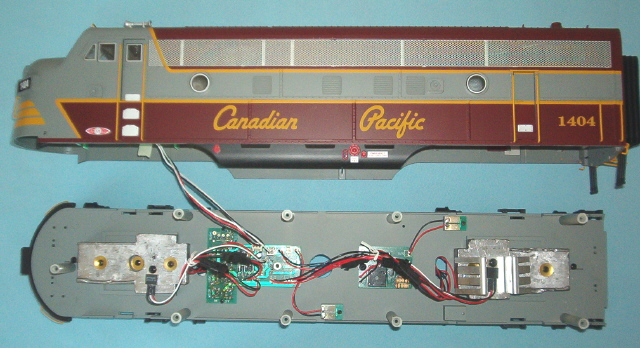
Identify the 2-pin and 3-pin connectors on the power distribution board for the front lights.
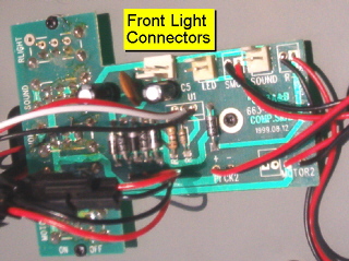
Unplug the connectors and set the shell aside for now.
INSTALLING THE MU CONNECTOR
It is imperative that the track power pick-ups be disconnected so the locomotive cannot pick up track power or feed battery power into the tracks. The result could be electronically catastrophic.
Undo the twist ties that group the locomotive wiring together.
There should be two connectors from the front motor block, but only one connector has two red wires and two black wires on one side of it. It is attached to the power distribution board at PICK1 and is for the front truck, track power pick-ups. Unplug it to isolate the front truck, track power pick-ups.
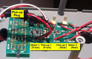
There should be two connectors from the rear motor block, but only one connector has two red wires and two black wires attached on one side of it. It is attached to the power distribution board at PICK2 and is for the rear truck, track power pick-ups. Unplug this connector to isolate the rear truck, track power pick-ups.
Drill a 1/8 inch hole in the center of the frame, 5/8 of an inch from the back.
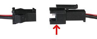
Two, 2-pin connector sets are required for this project. They are available from All Electronics under catalog number CON-240. OVGRS members can purchase the two-pin connector sets by contacting Paul Norton.
As only the male halves (indicated with red arrows) of the All Electronics connector sets are needed for this project, unplug the females halves and set them aside. They can be used later for power cars and other projects. Here after the male halves of the sets will be referred to as the AE connector.
Although the wire colours on the AE connector sets may not positioned the same as on USA Trains connectors, there is no need to change the position of the wires over as the polarity will change with each change of direction of the locomotive.
Cut a two inch length of shrink-wrap tubing. Slip it over both wires of an AE connector. With the tab of the connector facing up, slip the wires through the hole in the bottom of the frame until the shrink-wrap is snug against the frame and the AE connector. Apply hot glue over the wires on top of the frame for stress relief.
Insert the other AE connector into the open connector attached to the power distribution board at PICK2.
Gather the ends of the wires of this AE connector and the AE connector installed on the rear of the locomotive. Trim the wires to length, and strip 1/4 inch of insulation off all four wires. Slip a 3/4 inch length of shrink wrap over one of the red wires, and over one of the black wires. Solder the red wires together. Slip the shrink wrap down over the joint and warm until it seals. Repeat for the black wire.
THAT’S IT! You have completed the installation of an MU connector on your USA Trains F-3A. All that’s left to do is test to ensure it is wired correctly.
TESTING THE MU CONNECTOR
Plug the lights back in to the power distribution board and set the shell back on the frame. Ensure all wires are inside the mounting posts so they do not get pinched between shell and the lip of the frame.
Connect a power and control car to the MU connector. Once the MU connector has been successfully tested; fasten the shell, fuel tank, and couplers to the frame.
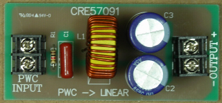
If a Revolution receiver is being used in the power and control car, the lights may not work. If not, add a Crest Electronics PWC to Linear DC Board in the wires of the MU plug on the trailing power and control car. OVGRS members can purchase the PWC to Linear DC Board by contacting Paul Norton.
CONGRATULATIONS! The MU connector will allow you to run your F-3A locomotive with a trailing power and control car and enjoy all the benefits of battery power and radio control.