
This article describes converting the Bachmann Heisler from G-scale truck-mounted couplers to Kadee #1 scale body-mounted couplers. The conversion is almost identical for both ends of the locomotive.
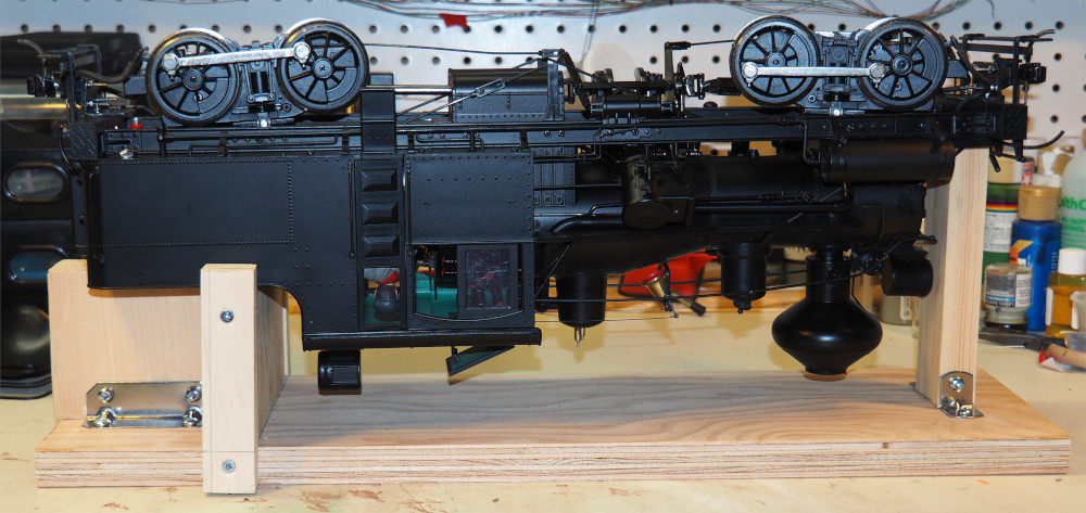
For the purpose of performing the coupler conversion, I found it useful to have a work cradle that holds the locomotive stable, and prevents damage to topside details. I knocked this one together out of scrap lumber (note that this is intended to be used with the coal load removed):
Materials:
- Kadee #1905 sill-mounted couplers, 1 pair
- 3/4” aluminum angle
- 2-56 hardware (nuts, bolts, lock washers)
- flat black paint
Lay the locomotive on its side, or upside down on a work cradle. Remove the step by undoing the four screws (red arrows below).
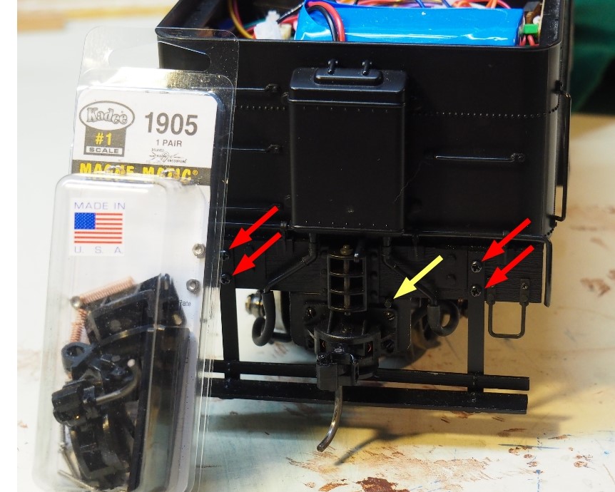
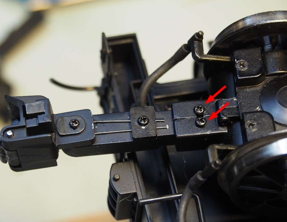
Remove the Bachmann couplers by undoing the two screws on the underside of the coupler pocket:
The mounting surface for the #1905 coupler is made from a piece of 3/4” aluminum angle, which will be bolted to the underside of the existing sill. Unscrew and remove the bottom of the sill, which is a hollow plastic moulding. A simulated air pipe runs the length of the locomotive, emerging at both ends just to right of the centre-line (yellow arrow on Figure 1), and is clipped to the sill bottom. Slide the sill bottom off the end of the pipe and remove the clip.
With a hacksaw, cut a piece of angle about 1” long (just a bit wider than the coupler base). Drill four holes sufficient to pass #2 hardware in one face to match those in the coupler base. Drill two holes in the other face as shown in Figure 2 below: these holes are used to bolt the angle to the bottom of the plastic sill, such that the front surface of the angle will wind up approximately flush with the front surface of the sill. Centre the angle on the sill bottom and drill corresponding holes in the latter.
The angle needs a groove cut into the top face to allow the air pipe to come through. Assemble the angle to the sill bottom, inserting 2-56 bolts to keep the parts aligned, and place the assembly back onto the sill. Mark the location of the air pipe. Remove the assembly from the locomotive and remove the angle from the sill bottom. Using a hacksaw and/or file, cut a groove through one surface of the angle. The final result should look as shown below:
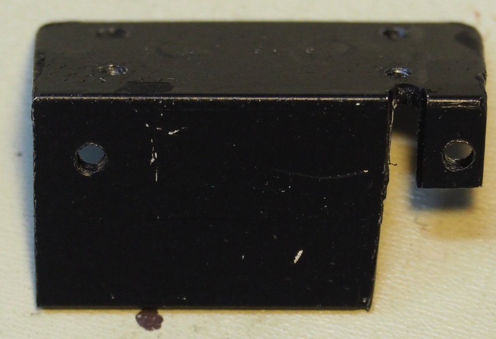
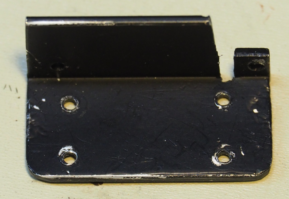
Note: This is the adapter for the rear of the locomotive; the front will be a mirror image of this.
Paint the aluminum angle flat black (a spray can works well for this).
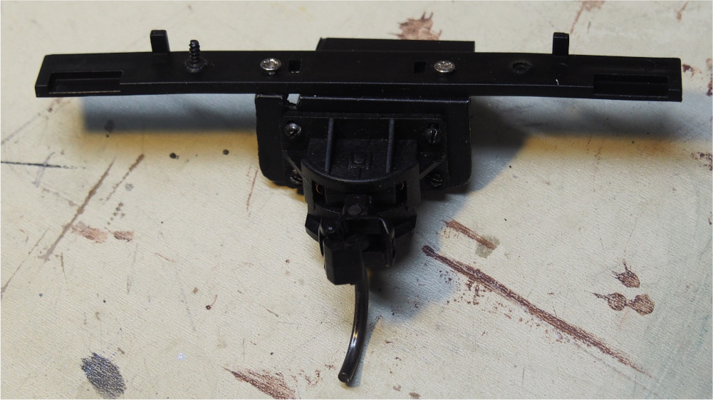
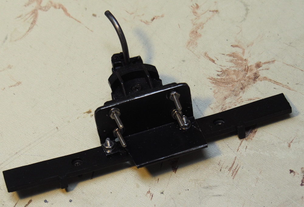
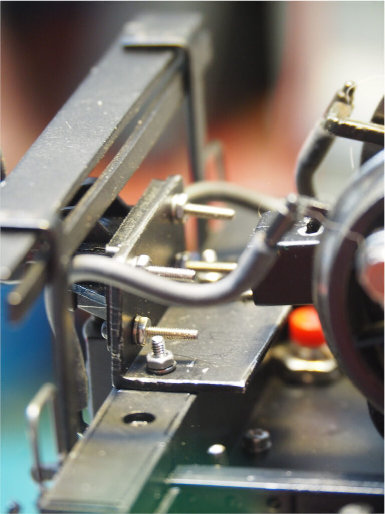
Assemble the angle to the sill bottom again, this time fastening it with nuts and lock washers. Assemble the coupler per the Kadee instructions and bolt it to the face of the angle with 2-56 hardware (leave these nuts slightly loose for now). Touch up the bolt heads with black paint. The whole assembly should look like this:
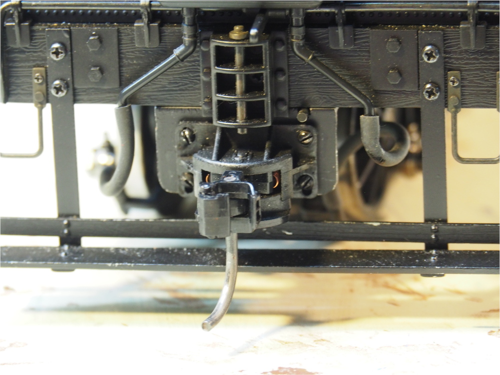
Reinstall the sill bottom in the sill. Reinstall the step. The final assembly should look like this:
The mounting holes in the Kadee coupler are slotted to allow height adjustment. Set it to the correct height using a Kadee coupler gauge, and tighten the nuts. Repeat the conversion procedure on the other end of the locomotive, and you are ready to haul cars and switch industries!