
27 AUGUST 2020
Be aware that some of the USA Trains locomotive project articles that I posted years ago are somewhat out of date. The Crest Revolution receivers at that time all had Pulse Width Control for the output power. The voltage spikes in PWC would not let the light bulbs work properly in some USAT diesels. As I result I removed the USAT main circuit board and headlight circuit boards and replaced the headlight and number board lights with LEDs.
Precision RC now makes DC Linear Revolution receivers, so you no longer have to remove the main circuit board and change the lights in USAT diesels. Some of the new USAT diesels also have LED lights that work with the Revolution PWC receivers.
Some of the Super Sockets I built at that time were also rather wide to accommodate all the P8 wiring. Now I make a small separate circuit board for the six Revolution accessory wires and P8 sound wires. This circuit board also has small components that replace the Phoenix Sound volume switch, and allows the volume to be adjusted on the fly using the Revolution throttle.
Paul Norton
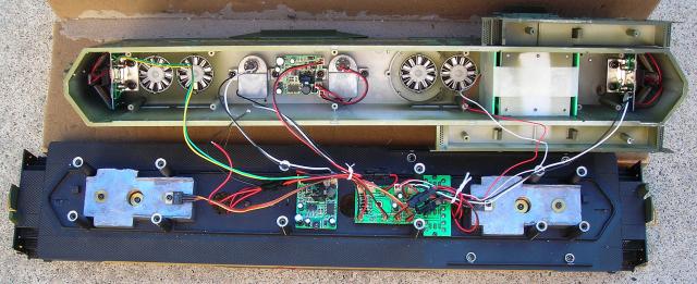
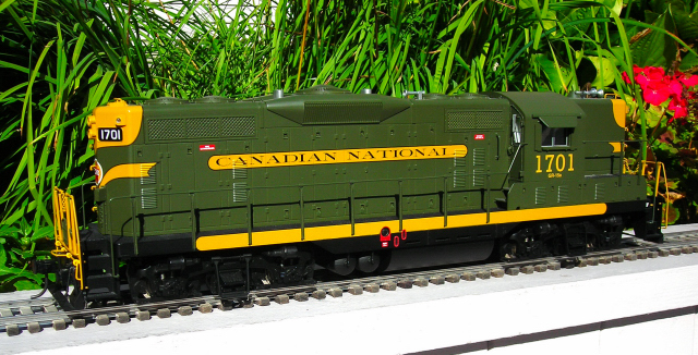
This article details a method used to convert a USA Trains GP-9 diesel from track power to on board, battery power and radio control using an Aristo-Craft lithium-ion battery and a Revolution receiver in a Plug and Play Board.
The battery switch and receiver will control all the functions of the battery, charging connector, motors, and lights; making the USA Trains main printed circuit board with its four switches redundant. The voltage regulators on that board that drive the incandescent lamps are also incompatible with the Pulse Width Control output of the Revolution receiver. As the factory headlight and number board lamps would not function properly, even if the main printed circuit board was retained, they will be replaced with LED headlights and number board lights.
The number board LEDS will light as soon as the battery switch is turned on. The headlight LEDs will come on with the first push of the Revolution throttle (1% power) long before the motors start to move. Although LEDs are much brighter than the factory bulbs, they will draw a fraction of the power and extend battery run times. The locomotive will also start sooner and run smoother at low speeds.
The instructions for installing the LED lights were updated on December 2012. They are now shorter and easier than previously posted.
As the redundant factory electronics will be stored intact in a large Ziploc bag, nothing prevents the locomotive from being restored to its original condition for re-sale at a later date.
Please read this article carefully, highlighting the components that are needed. Sources of supply are suggested for items not sold by your hobby suppliers. OVGRS members can purchase the required components by contacting Paul Norton.
The article appears long because it is detailed and includes lots of pictures. But if you take your time and follow it step-by-step it is not difficult, and the results will be well worthwhile. Although a GP-9 was used for this installation, the instructions could be used as a guide to re-power other USA Trains, 4-axle diesels.
OPENING THE LOCOMOTIVE
Carefully remove the handrails from the sides and ends of the locomotive. A small, flat screwdriver can be used to gently pry the stanchion tabs from their holes in the frame if necessary. Folding a piece of vinyl tape over the end of the screwdriver may prevent the paint from being scratched. Set the handrails aside for now so they do not get damaged.
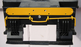
Place the locomotive on its side on a soft surface. Remove the leaf spring stirrups from the two up-facing side frames. Remove the screws outlined in yellow, and slip the two side frames from the ends of the wheel axles.
Unplug the four wires from each of the motor blocks. Remove the motor blocks, and wipe the excess grease off the ends of the axles. Set the motor blocks aside for now.
It is imperative that the track power wiring be removed to ensure the locomotive cannot pick up track power or feed battery power into the tracks. The result could be electronically catastrophic. Unsolder all the wires from the tabs on the inside of all the side frames. Wipe the grease off the short black wires that ran between the tabs, and place them in a large Ziploc bag labeled GP-9 along with the road name and number.
Wipe the excess grease off the side frames. Re-install the two that were removed, and their leaf spring stirrups.
Remove the two screws that hold the bottom of the fuel tank to the frame. Remove the tank, and fasten the two screws back in the frame so they do not get lost or mixed up with others.
Remove the two screws indicated with the yellow arrows at each end of the frame, and place the brackets and couplers in the fuel tank. Set the fuel tank aside for now. Fasten the screws back in the frame so they do not get lost or mixed up with others.
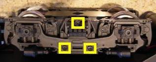
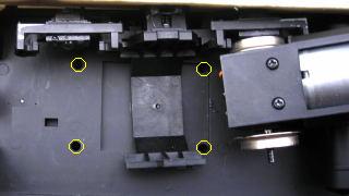
Place the locomotive upside-down on a soft surface taking care not to damage the horns. Remove the four screws indicated with the yellow arrows that hold the battery boxes to the frame. Place them in a small container for now.
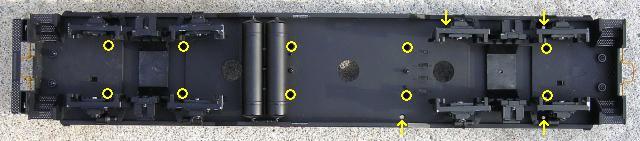
There are ten longer screws outlined in yellow that hold the shell to the frame. These are hidden in deep burrows and will require a long, number 1 Phillips screwdriver to remove them. Remove these ten screws and place them in the small container with the others.
Turn the locomotive over and set is beside the work cradle. Holding the ends of the hoods, carefully lift it straight up. The long hood, cab, battery boxes, and short hood will lift off as one piece. Do not lift it up too far or the wiring connectors may unplug.
Set them on the work cradle beside the frame. Fasten the screws in the small container back in the long hood, battery boxes, and short hood so they do not get lost or mixed up with others.
REMOVING THE FACTORY ELECTRONICS FROM THE FRAME
Remove the two, white twist ties from the wiring.
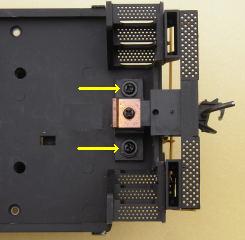
Remove the screw that holds each voltage regulator to a weight. Remove the voltage regulators, and fasten the screws back in place.
Pull the disconnected motor block wires through the holes in the frame. Remove the three screws and T-shaped printed circuit board from the frame. Remove the two screws and small, square printed circuit board from the frame.
Place all the electronics in the long hood, and set the locomotive body aside for now. Place their screws in the Ziploc bag.
That completes the removal of the factory electronics from the frame.
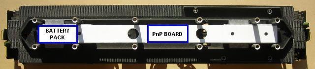
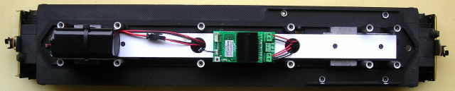
COMPONENTS PLATFORM
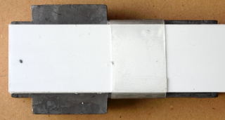
A platform will be made from two pieces of 1/8 inch thick styrene to mount the Aristo-Craft, lithium-ion battery and Plug and Play Board.
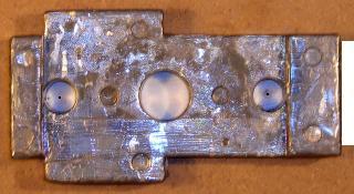
Remove the screws and washers from the weights and place them in a small container. Measure accurately the length from the outside end of one weight to the outside end of the other.
Score and snap two strips of styrene 1 3/16 inches wide by the measured length (approximately 16 1/2 inches long). The styrene will have to be scored on both sides to snap cleanly.
HINT: If you place a dot on one end of the styrene strips and the rear weight, it is easier to place them correctly during the assembly of the components platform.
Remove the weights and securely tape one to each end of a styrene strip. Hockey shin pad tape is great for this as it stretches somewhat, sticks well, and will not leave glue behind. Ensure that each end of the strip is flush with the ends of the weights.
Turn the weights and styrene strip over. Insert an 11/32 inch drill bit in each of the holes in the ends of the weights. Turn the drill bit with your fingers to make a circular mark in the styrene sheet.
Remove the tape and the styrene strip from the weights. Place the weights back on their mounting posts.
Tape both pieces of styrene together ensuring the edges and ends are flush, and the marks made with the drill bit are facing out. Using the marks as a guide, drill four holes through both pieces with a 1/8 inch bit. Remove the tape and separate the strips.
Use the four screws to fasten one of the strips to the top of the weights. If it does not fit properly, try turning it around or flipping it over. Place marks on the strip 1 1/2 and 1 3/4 inches from the end of the long hood weight.
Remove the strip, and use the farthest mark to score and snap a 1 3/4 inch long piece off the strip. Use the second mark to trim the small piece to 1 1/2 inches long. Place the two pieces back on the weights, making sure the ends of both pieces are flush with the ends of the weights. The slot between them will be for a cable tie to secure the lithium-ion battery to the components platform.
Take the unmodified styrene strip and enlarge the four holes in it with a 1/4 inch drill bit. These holes will pocket the heads of the four screws holding the weights to the frame. The pockets will prevent the screws from damaging the bottom of the battery.
Test fit the second strip over the two lower pieces making sure the edges and ends are flush and the holes line up. Glue the second strip to the two lower pieces. I tried several glues and found that Testors plastic cement was the easiest to use and held the pieces together well. Use the screws and washers to hold it in place while the glue dries.
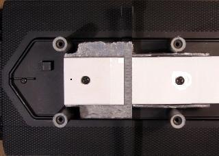
When the glue has dried, place a ruler across the front of the posts behind the cab and draw a line across the platform. Place the ruler behind the next pair of posts and draw a second line across the platform.
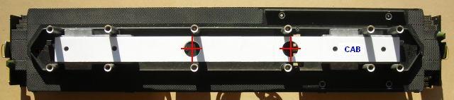
Remove the platform from the frame. Measure to the center point of each line and place a mark. Drill a hole using a 3/4 inch spade bit at each of the marks. Smooth any sharp edges around the holes with fine sandpaper. These holes will be used to feed wires from the motors and battery switch.
Fasten the platform back on the weights with the screws. Place the washers in the Ziploc bag. That completes the assembly and installation of the components platform.
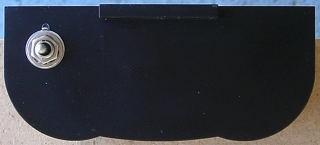
BATTERY CHARGING CONNECTOR
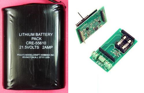
The female half of an All Electronics, 2-wire connector set will be used as a charging connector for the on-board battery. The connector set is available from All Electronics under catalog numbers CON-240.
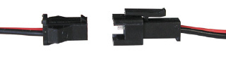
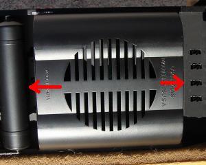
The female connector, shown on the left, is the same as the one on an Aristo-Craft, lithium-ion battery.
CAUTION: The wires on the connector sets sold by All Electronics may not be positioned the same as the wires on the connectors of lithium-ion batteries and chargers. If not, click on the following link to see how to switch the positions of the AE Connector Set Wiring so that proper polarity is maintained.
To make the charging connector inconspicuous, trim the wings off and sand the sides smooth.
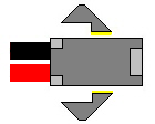
Drill a hole in the long hood pilot under the center of the coupler lift bar with a 1/8 inch bit. With the notch on the connector facing up, feed the wires through the hole until the connector is snug against the pilot. Secure the wires to the back of the pilot with hot glue to ensure the connector remains snug.
Drill a second hole in the top of the frame opposite the screw for the coupler centering spring. Feed the wires through the second hole until they are snug and seal them with hot glue. Route them inside the frame posts alongside the components platform.
That completes the installation of the battery charging connector. It will be connected when the battery switch is installed. To make it disappear, fold the end step down.
LITHIUM-ION BATTERY
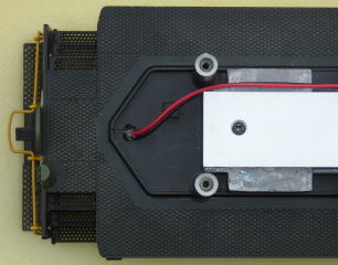
Pass a long cable tie through the slot in the bottom of the components platform on the long hood weight. Apply a length of double-sided tape to the side of the battery and fasten it to the platform between the frame posts. Fasten the cable tie around the battery and its connector and charging connector wires as shown. The tie should be snug but not tight. Trim the excess cable tie.
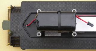
That completes the installation of the battery. It will be connected when the battery switch is installed.
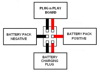
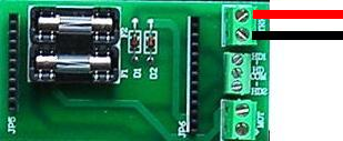
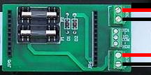
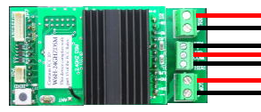
PLUG AND PLAY BOARD
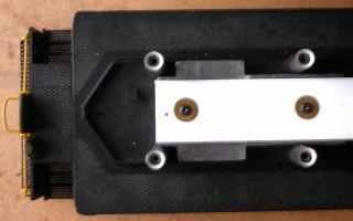
Fasten the Plug and Play Board on the components platform between the two holes with the double-sided tape provided. The screw terminals should face the cab.
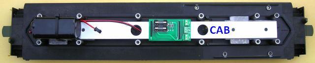
That completes the installation of the Plug and Play Board. It will be wired as the battery switch, motors, and LED lights are installed.
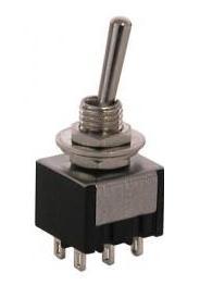
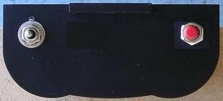
BATTERY SWITCH
As the battery will be charged on-board, a double-pole double-throw (DPDT) switch is needed to toggle the battery between its charging connector and the Plug and Play Board. The switch will be installed in the wall of the fuel tank behind the cab. This will allow it to be accessible, but hidden when running the locomotive.
The DPDT center-off switch is available from All Electronics under catalog number MTS-12.
The wall behind the cab is labeled USA Trains on the bottom of the fuel tank. Place a mark 1/2 inch over from the left-hand side of the tank and 1/2 inch down from the top. Drill a hole for the switch using a 15/64 inch bit. Set the fuel tank aside for now.
As it is easier to solder and shrink wrap the wires to the terminals of the switch before it is installed; place the switch in a small bench vise with the terminals facing up.
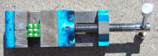
The male half of an All Electronics, 2-wire connector set will be used to connect the lithium-ion battery to the center terminals of the switch. The male connector, shown on the right, is the same as the one on an Aristo-Craft, lithium-ion battery charger. But the wires on the connector sets sold by All Electronics are not colour coded the same as the connectors on Aristo-Craft and Cordless Renovations lithium-ion batteries and chargers. Click on the following link to see how to change the AE Connector Set Wiring over so that proper polarity is maintained.
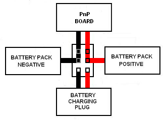
Do not shorten the wires as they must be long enough to easily reach from the battery connector to the switch before the fuel tank is installed. Solder and shrink wrap the wires of the connector to the center terminals of the switch as shown in the following diagram.
Place the vise and switch next to the frame in the fuel tank area. Push the battery connector soldered to the center terminals of the switch through the hole in the center of the frame and the hole in the components platform closest to the battery.
CAUTION: Check that the DPDT switch is in the center-off position. Ensure the colour coding of the wires on the lithium-ion battery connector and the connector soldered to the center terminals of the DPDT switch match. Plug the two connectors together.
Draw the vise back until the wires are fully extended. The position of the vise will ensure the remaining wires will be long enough to allow the switch to be installed before the fuel tank is fastened to the frame.
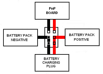
Solder and shrink wrap a 12 inch long, red wire to the bottom terminal on the right side of the switch as shown in the diagram below. Solder and shrink wrap a 12 inch long, black wire to the bottom terminal on the left.
Push these wires through the hole in the center of the frame and the hole in the components platform closest to the battery. Trim these wires or the wires from the battery charging connector to a suitable length. Solder and shrink wrap the red wires together. Solder and shrink wrap the black wires together.
Solder and shrink wrap a 9 1/2 inch long, red wire to the top terminal on the right side of the switch as shown in the diagram above. Solder and shrink wrap a 9 1/2 inch long, black wire to the top terminal on the left.
Push the wires through the hole in the center of the frame and the hole in the components platform next to screw terminals on the Plug and Play Board. Strip a bit of insulation off the ends of the wires and tin them. Fasten the black wire in the TRK screw terminal marked with a small triangle, and the red wire in the other.
That completes the wiring of the battery switch. It will be installed when the locomotive is re-assembled.
CHARGING THE BATTERY
Toggling the battery switch up connects the battery to its charging connector.
If the battery has not been charged, connect an Aristo-Craft, lithium-ion battery charger to the charging connector on the pilot and toggle the switch up. The green LED on the charger should light up. Plug the charger into an outlet. After about four hours, the battery should be fully charged. Return the switch to its center-off position and remove the charger.
To test the battery, connect the male half of a 2-wire connector set to the charging connector on the rear pilot. Attach a voltage meter to the free end of the wires and toggle the battery switch up. A fully charged Aristo-Craft, lithium-ion battery should read 25.2 volts. Return the switch to its center off position.
MOTOR BLOCKS
Remove the six screws and the bottom cover from each motor block. Place the screws in a small container so they do not get lost.
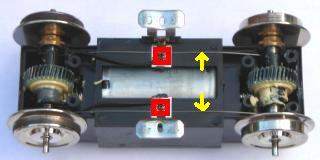
Remove the small screws outlined in red from the motor blocks and place them in the small container. Lift the chrome brackets, and remove the track power sliders and wire wipers sprung between the axles. Wipe the grease off them, and place them in the Ziploc bag. Fasten the chrome brackets back in place with the small screws.
Lift the axle sets out. If you can gently turn a wheel while holding the other, the axle sleeve on the drive gear is split. They can be fixed using the method in the DRIVE GEAR AXLE SLEEVES repair tip, or replaced with complete axle assemblies. If you wish to get rid of rubber traction tires, order axle assemblies without them from USA Trains.
Place the axle assemblies back in the motor blocks. Ensure their bushings are seated flat in the slots in the sides of the motors blocks. Pop the covers back on and fasten them with their screws. Do not fully tighten any of the screws until all the screws have been inserted and turned down some. If you fully tighten the screws as you go, the last few may be hard to insert and may strip the threads in the plastic motor block.
The small and sometimes unreliable slip-on connectors that plug into the front of the motor blocks will be replaced with wires soldered directly to the motor terminals. Remove the six screws and the top cover from each motor block. Place the screws in a small container so they do not get lost. Remove the small, lash adjusting assemblies from the ends of each motor block and place them in the small container.
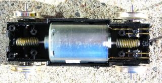
Lift the motors out of the blocks. There are four brass rods in each motor block. The two on the outside provide power to the motor terminals and are secured with small screws and plastic washers. Remove the screws and washers and place them in the small container. Remove the outside rods and place them in the Ziploc bag.
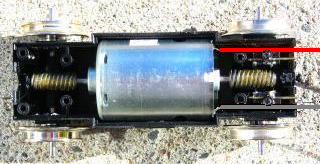
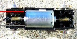
When the motors are wired, it would less confusing if the colour coding of the motor wires matched when fastened under the MOT screw terminals of the Plug and Play Board. In order to accomplish this, one motor block has to be wired differently from the other. With the motor terminals facing each other, solder a foot of red wire to each of the top terminals and a foot of black wire to each of the bottom terminals.
If required, lubricate the worm gears on the motor shafts and the pinion gears on the axles with plastic compatible grease. Ensure the worm gears and the pinion gears are properly meshed. The wheels should not turn.
Lightly push the red and black motor wires into the outside channels left by the brass rods that were removed. Secure the wires and inside brass rods using the small screws and plastic washers in the small container. Place the lash adjuster assemblies back in their slots in the ends of the motor blocks. If necessary, use a little grease to hold them in place. Set the top covers back on. If the covers are not fitting tightly, check to ensure the lash adjuster assemblies are seated properly. Fasten the covers back on with their screws.
Lay the locomotive on its side on a soft surface. Remove two up-facing side frames and install the motor blocks. Fasten the side frames and their spring stirrups back on.
Pass the motor wires through their holes in the frame and the hole in the components platform nearest the screw terminals on the Plug and Play Board. Pull the wires taught and trim them 4 inches above the components platform. This extra wire will allow the motor blocks to turn freely.
Strip enough insulation off the ends of the wires to allow them to be fastened under the screw terminals labeled MOT on the Plug and Play Board, and tin them. Fasten the black wires in the MOT screw terminal marked with a small triangle, and the red wires in the other MOT screw terminal. Tug on each wire to ensure they are all fastened securely.
That completes the re-wiring, lubrication, and installation of the motor blocks. Wash any black grease off your hands before proceeding, as it will never come out your clothes.
REVOLUTION RECEIVER LINKING BUTTON
Part of the process required to link the Revolution receiver to its throttle involves pushing a linking button. The button will be installed in the wall of the fuel tank behind the cab with the battery switch. This will allow it to be accessible, but hidden when running the locomotive.
Place a mark 1/2 inches over from the right-hand side of the tank and 1/2 inch down from the top. Drill a hole on the mark for the switch using a 9/32 inch bit. Set fuel tank aside for now, the linking button will be installed in the fuel tank when the locomotive is re-assembled.
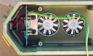
REVOLUTION RECEIVER
Install the Revolution receiver in the Plug and Play Board ensuring all the pins line up properly. Raise the antenna!
Push the white connector and wires for the linking button through the hole in the center of the frame and the components platform. Plug the linking connector into header on the back of the receiver.
The Installation and Operation Manual for the Revolution Train Engineer is on the CD that comes with the set. The Revised Manual and other information is also available on the Aristo-Craft web site as an Adobe pdf file. To read or download the revised manual, click on the link.
Although the headlights are not available for use in this testing procedure, a small red LED on the receiver will flash during the linking process. Toggle the battery switch down, and program the receiver in accordance with the instructions provided in the Installation and Operation Manual.
Place the frame on a test stand or rollers so the wheels can turn freely. Test the motors to ensure they respond properly to the throttle. After testing return the battery switch to its center off position.
That completes the installation, programming, and testing of the Revolution receiver. All that remains to do is add the LED lights to the shell and re-assemble the locomotive.
REMOVING THE FACTORY ELECTRONICS FROM THE HOODS
Remove the two screws holding each of the printed circuit boards for the lights to each end of the hoods. Place the screws in the Ziploc bag.
Carefully lift the printed circuit boards back so the number boards and headlights can be removed. The number boards are lightly glued to the ends of the hoods and should pop out with a gentle push. Set them aside for now. The headlight lenses are also lightly glued to the hoods and should pop out with a gentle push.
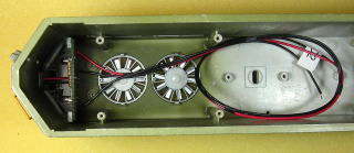
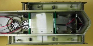
Remove the four screws, the smoke units, and the small printed circuit board from the long hood.
Unplug the white plastic connector for the cab light from the T-shaped printed circuit board at the 2-pin header labeled “lamp”. Coil the wire and tape it to the side of the hood out of the way.
Place all the electronics and their screws in the Ziploc bag.
If the front and rear walls of the cab have not already fallen out, remove them and set them aside for now.
That completes the removal of all the factory wiring and electronics.
LED HEADLIGHTS AND NUMBERBOARD LIGHTS
UPDATED DECEMBER 2012
The GP-9 had incandescent lamps driven by voltage regulators that are incompatible with the Pulse Width Control output of the Revolution receiver. For this reason the factory lighting circuit boards have been removed and will be replaced with LED headlights and number board lights.
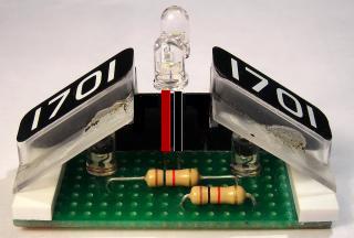
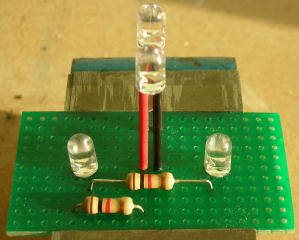
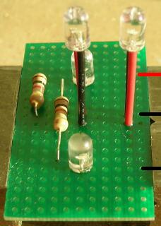
The headlight LEDs, number board LEDs, resistors, and number boards will be mounted on perf boards. The warm white flangeless LEDs, resistors, and straight trace perf board are all available from All Electronics under catalog numbers LED-221, 293-1K, and ECS-4 respectively.
Cut two pieces from the perf board, 20 traces across by 11 rows down. Sand the edges smooth. Each board should measure approximately 2 by 1 1/8 inches.
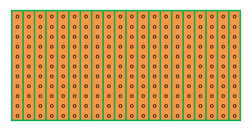
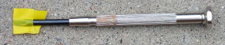
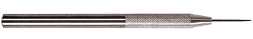
A hobby awl made by Excel and a steel ruler are excellent and safe tools for scoring across the holes in perf boards. Once the awl has been used, a hobby knife will be less likely to wander. The perf boards must be scored on both sides before being snapped.
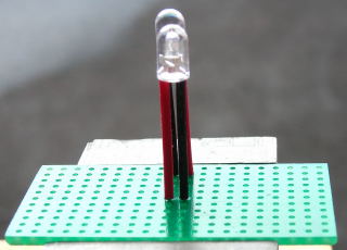
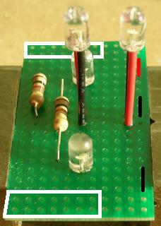
The bottom of the LED headlights must be installed 3/4 of an inch above the component (green) side of the perf boards in order for them to fit properly in the hoods. Strip 4 inches of insulation off a red 22 gauge wire, and 4 inches of insulation off a black 22 gauge wire. Cut the insulation into pieces 3/4 of an inch long. Slip the red pieces over the anodes (longer leads) of 4 flangeless warm white LEDs. Slip the black pieces over the cathodes (shorter leads).
A chopper is an excellent tool for repetitive precision cuts. They can be purchased from either NorthWest Short Line or MicroMark.
On the components side of the perf boards count over 10 and 11 traces from the left side and place marks with a black Sharpie marker on the top edge of the boards. Count down 2 rows from the top of the boards and place the black lead of an LED in trace 10 and the red in trace 11 in each. Use a toothpick to apply a bit of gap filling CA (super glue) to the bottom of the insulation on each of the leads. Ensuring they remain perpendicular, press the LEDs against the boards until the glue dries. The glue will dry quicker if the perf boards are held over an open bottle of CA accelerator (kicker).
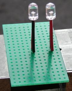
Count down 6 rows from the top of the boards and place the red lead of an LED in trace 10 and the black in trace 11 in each. Use a toothpick to apply a bit of gap filling CA to the bottom of the insulation on each of the leads. Ensuring they remain perpendicular, press the LEDs against the boards until the glue dries.
On the components side of the perf boards count over 5 and 6 traces from the left side and place marks with a black Sharpie marker on the top edge of the boards. Count down 6 rows from the top of the boards, the same row as the lower headlight, and place the longer lead of an LED in trace 5 and the shorter lead in trace 6 in each. Use a toothpick to apply a bit of gap filling CA to under the bottom of the LEDs. Press the LEDs against the boards until the glue dries.
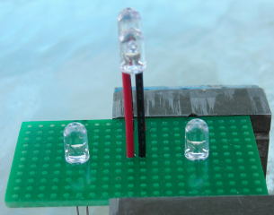
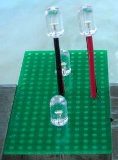
On the components side of the perf boards count over 15 and 16 traces from the left side and place marks with a black Sharpie marker on the top edge of the boards. Count down 6 rows from the top of the boards, the same row as the lower headlight, and place the longer lead of an LED in trace 15 and the shorter lead in trace 16 in each. Use a toothpick to apply a bit of gap filling CA to the bottom of the LED. Press the LED against the boards until the glue dries.
Check to ensure all the LEDs in the sixth row down from the top have their longer leads on the left. The LED in the second row from the top should have its longer (red) lead on the right. Flip the boards over. Flux, solder, and trim the leads of the headlight and number board LEDs.
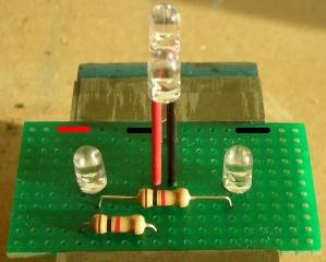
On the components side of the perf boards count over 6 and 15 traces from the left side and place marks with a black Sharpie marker on the bottom edge of the boards. Bend the leads of 1K ohm resistors so they will fit in the holes of fourth row up from the bottom at traces 6 and 15 of each board. The resistors can be held to the boards with self-closing tweezers so they will remain in place and flush to board when you flip the board over to solder them. Turn the boards over. Flux, solder, and trim the leads.
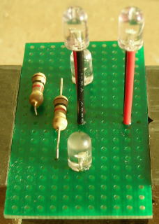
On the components side of the perf boards count over 5 and 10 traces from the left side and place marks with a black Sharpie marker on the bottom of the boards. Bend the leads of 1K ohm resistors so they will fit in the holes of the second row up from the bottom at traces 5 and 10 of each board. Turn the boards over. Flux, solder, and trim the leads.
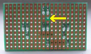
On the solder side of the perf boards count down 4 rows from the top and over 11 traces from the left side. Break open the trace using a 1/8 drill bit in a pin vise so the LED headlights can function properly.
Cut two, 18 inch long lengths of red wire; and four, 18 inch lengths of black wire. Strip just enough insulation off one end of all the wires, so that the wire will pass through the board and protrude enough to be soldered.
In the top row of the components side of a perf board, place the end of the red wire in the hole for the 5th trace from the left edge. Flip the board over. Flux and solder the wire.
In the top row on the components side of a perf board, place the end of a black wire in the hole for the 10th trace from the left edge. Flip the board over. Flux and solder the wire.
In the top row on the components side of a perf board, place the end of a black wire in the hole for the 16th trace from the left edge. Flip the board over. Flux and solder the wire.
Repeat the wiring process for the other perf board.
In order to provide stress relief and pass the wires through the perf board, the holes for the 3rd, 8th, and 18th trace from the left edge in the top row will have to be enlarged with a 5/64ths inch drill bit.
On the components side of each of the perf boards, push the free end of the red wire through the enlarged hole in the 3rd trace from left edge, the free end of the black wire in the center through the enlarged hole in the 8th trace, and the free end of the other black wire through an enlarged hole in the 18th trace.
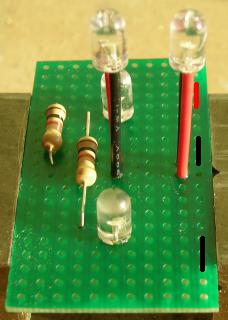
Draw the wires back until there is a small loop above the boards in each.
Clean both sides of the boards with flux remover or rubbing alcohol. Running a hobby awl up the traces will remove any flux residue and make it obvious if there is any solder overlapping the traces.
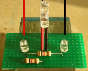
Strip just enough insulation off the free ends of just the red wires and black wires on the edges of the perf boards so that later they can be fastened under the screw terminals of the Plug and Play Board. Tin the ends of these wires only. Leave the black wires in the center of the perf board alone for now. Leaving them untouched will allow you to be able to distinguish these black headlight ground wires from the black number board ground wires later in the wiring installation process. If these wires were fastened in the wrong screw terminals, the headlights would remain on all the time and the number board lights would be directional.
Count down 4 rows from the top of the component side of the perf boards and place a mark on both edges of the boards. Cut two shims 3/4 inches long from a 1/4 by 1/8th inch strip of styrene. The shim must be 1/8th of an inch thick in order for the LED headlights and the number boards to fit properly. Glue the shims to flush to each the edge of the perf boards. The top of the shims must be just under the holes in row 4.
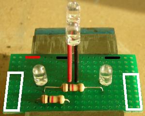
Using the top of the shims as a guide, take the gloss off the perf board across the holes of row 4 with a small, flat file. This will allow the CA used to fasten the number boards to the perf boards to hold.
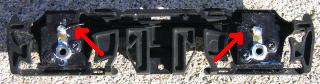
In order for a number boards to fit on the perf board, the center section has to be modified to allow the leads of the bottom LED headlight to pass. CAREFULLY cut the small square section outlined in yellow from the center of the number boards.
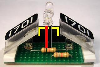
Lightly sand the paint from the rear ridge of one of the number boards. Wipe it clean and apply a thin coat of CA to it with a toothpick. Fasten the rear ridge to row 4 flush with the top of the shims. The edges of the number board may slightly overlap the edges of the shims. Use a micro brush to wash the top of the rear ridge of the number board with CA kicker. Glue the edges of the number board to the sides to the styrene shims. Use a micro brush to wash the edges with CA kicker. Repeat the process for the second number board.
Place the locomotive body on a soft surface next to the frame taking care not to damage the horns. Insert one of the boards in the long hood, and fasten each of the bottom corners to the sides of the hood with a small dab of hot glue.
Insert one of the boards in the short hood, and fasten each of the bottom corners to the sides of the hood with a small dab of hot glue. Slide a 4 inch length of shrink wrap up the wires of the board in the short hood, and pass the wires through the top of the cab. This shrink wrap will help hide the wires from view.
Slide the cab walls in place, ensuring that shrink wrap fits in the slot in the tops of them. Fasten the walls to the bottom of the cab with tape so they remain in place.
Slip small bands of shrink wrap over the wires of each perf board at 4 inch intervals and heat them until they are snug.
Fasten the red wire from each board in the screw terminal HD COM to power all the headlights and number board lights. Give each wire a light tug to ensure it is fastened securely.
Fasten the two tinned black ground wires for the number board light grounds in to the TRK screw terminal marked with a small triangle on the Plug and Play board, along with the negative wire from the battery switch. You may have to solder them together to get them all to stay fastened.
Strip just enough insulation off the free ends of the remaining black headlight ground wires so that they can fastened under the screw terminals of the Plug and Play Board labeled HD1 and HD2. Tin the ends of these wires.
If you are running this locomotive long hood forward, place the black ground wire for the long hood headlights under the screw terminal labeled HD2, and the black ground wire for the short hood headlights under the screw terminal labeled HD1.
If you are running this locomotive short hood forward, place the black ground wire for the short hood headlights under the screw terminal labeled HD2, and the black ground wire for the long hood headlights under the screw terminal labeled HD1.
That completes the assembly and installation of the LED headlights and number board lights.
Toggle the battery switch down to power the receiver, and all the number board LEDs will come on full bright. With the first push of the throttle (1% power) a set of LED headlights will come on full bright.
If the headlights and the motors are not in operating in the same direction, reverse the direction of the lights on the throttle using the ASSIGN FUNCTIONS menu, or change the positions of the black wires in screw terminals HD1 and HD2 on the Plug and Play Board. When testing is complete, turn the battery switch off.
RE-ASSEMBLING THE LOCOMOTIVE
Remove the four screws from the battery boxes and the ten longer screws from the hoods and place them in a small container. Carefully slide the hoods, cab, and battery boxes over the frame posts ensuring that none of the wires get caught between them and the frame. Everything should sit flush against the frame without being forced.
Lay the locomotive upside-down on a soft surface taking care not to damage the horns.
Remove a leaf spring stirrup and side frame from the long hood motor block. Place the three short screws in the small container so they do not get lost.
Slip the rear axle from its remaining side frame, and flip the motor block towards the center of the locomotive as shown. Fasten four of the longest screws in the small container through the frame back into the long hood.
Flip the long hood motor block back, and slip the axle back in the side frame. Fasten the other side frame back on using the three shortest screws in the container. Install the leaf spring stirrup.
Remove the leaf spring stirrup and side frame from the short hood motor block. Place the three short screws in the small container so they do not get lost.
Slip the front axle from its remaining side frame, and flip the motor block towards the center of the locomotive. Fasten two of the longest screws through the frame back into the short hood.
Flip the short hood motor block back, and slip the axle back in the side frame. Fasten the side frame back on using three shortest screws in the container. Install the leaf spring stirrup.
Fasten the four remaining long screws back through the frame in the fuel tank area into the long hood.
Fasten the battery boxes to the frame back using the four remaining screws in the small container.
Install the battery switch and linking button in the front of the fuel tank. Remove the two screws from the frame and install the fuel tank.
Remove the two screws from each end of the frame. Install the coupler brackets and couplers.
Install the handrails to the sides and ends of the locomotive.
CONGRATULATIONS! You have successfully installed on-board: battery power, radio control, and LED lights in your USA Trains GP-9.
2 comments
Most matched motor blocks will start at the same time.
Perhaps a cleaning and lubrication is in order.
Just a drop of fine oil on the motor bushings can make a difference.
Light grease on the gears helps as well.
The USAT gear grease tends to get waxy after a few years.
I was wondering…… in a 2 motor set up with engine up on wood blocks on workbench, ( wheels free to move) is it normal for one motor to start/stop slightly sooner then the second motor ?
Shouldn’t they both be getting the same electrical current amount simultaneously, therefore, both should move the wheels simultaneously at the same time and stop at the same time? (Using the Revolution system)
Thank you in advance for any feedback……Jim