
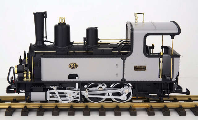
During the summer of 2011, I purchased a beautiful LGB 0-6-0 steam locomotive and a few European freight cars from the estate of a good friend Ralph Dipple.
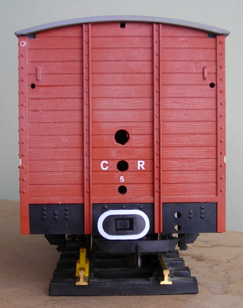
As I wanted to run this locomotive with battery power and radio control, I decided to build a trailing power and control car. One of the LGB boxcars purchased had been used as a power and control car, but all the components were gone. All that remained were three holes in the front of the car for the battery switch, charging connector, and MU connector wires.
Had the holes not been there, I may have considered mounting the switch and charging connector inside one of the doors of the car. But having the switch and charging connector readily accessible has its merits.
An Aristo-Craft, lithium-ion battery and Revolution receiver in a Plug and Play board were chosen to provide the battery power and radio control.
THE BATTERY SWITCH
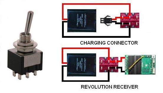
A Double-Pole Double-Throw (DPDT) center-off switch will be used to toggle the battery between its charging connector and the Plug and Play Board for the Revolution receiver.
The switch is available from All Electronics under catalog # MTS-12. OVGRS members can purchase the switch by contacting Paul Norton.
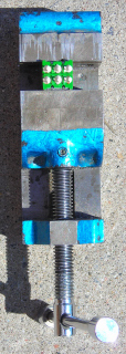
As it is easier to solder and shrink wrap the wires to the terminals of the battery switch before it is installed; place the switch in a small bench vise with the terminals facing up.
THE BATTERY CONNECTOR
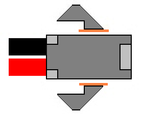
The male half of an All Electronics 2-wire connector set, shown on the right, has the same connector as an Aristo-Craft lithium-ion battery charger. It will be used to connect the battery to the center terminals of the switch.
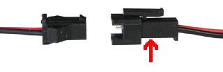
The 2-wire connector set is available from All Electronics under catalog # CON-240. OVGRS members can purchase the connector set by contacting Paul Norton.
CAUTION: The wire colours on the connector sets sold by All Electronics may not be positioned the same as the wire colours on the connectors of lithium-ion batteries and chargers. If not, click on the following link to see how to switch the positions of the AE Connector Set Wiring so that proper polarity is maintained.
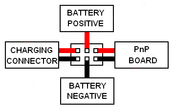
Trim the wires of the male half of an AE connector set to 6 inches in length. Solder and shrink wrap the wires to the center terminals of the DPDT switch as shown in the following diagram.
THE BATTERY CHARGING CONNECTOR
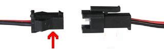
The female half of an All Electronics 2-wire connector set, as shown on the left, has the same connector as an Aristo-Craft, lithium-ion battery. It will be used as the charging connector for the on-board battery.
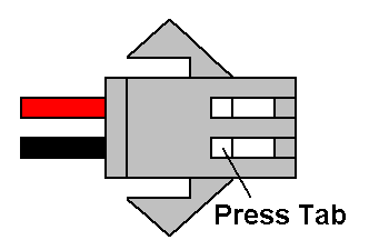
Push down on the small tabs on the back of the metal terminals of the female connector with a pin or hobby awl and gently push on the front of the terminals with a small screwdriver. After the terminals have moved, they can be withdrawn by pulling on their wires. Place the connector shell in a small container for now.
Trim the wires of the female connector to 6 inches in length. Solder and shrink wrap them to the left terminals of the DPDT switch as shown in the following diagram.
THE PnP BOARD WIRES
Cut a 4 inch length of red wire, and a 4 inch length of black wire. These will be used to connect the battery switch to the Plug and Play Board. Solder and shrink wrap the wires to the right terminals of the DPDT switch as shown in the diagram above.
INSTALLING THE DPDT SWITCH
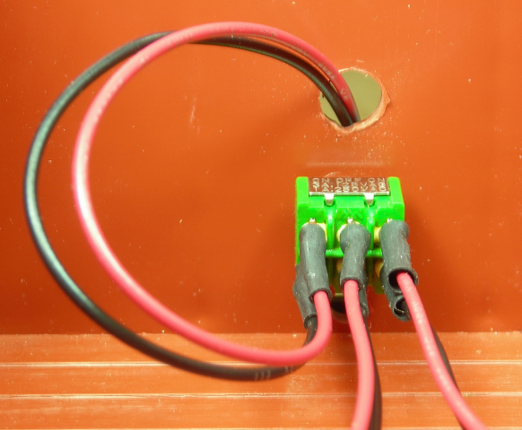
- In the front of the car, drill three holes as shown in the following picture.
- At the bottom use a 1/8 inch bit to drill a hole for the MU connector wires.
- Above it, use a 1/4 inch bit to drill a hole for the battery switch.
- Above that, use a 5/16 inch bit to drill a hole for the charging connector.
Snap the roof off the car, and install the DPDT switch in the center hole so it toggles left and right. Looking at it from inside of the car, the charging connector wires should be on the left, and the PnP Board wires to the right.
Pass the wires for the charging connector through the hole above the switch. Check to see if the small tabs on the metal terminals are raised slightly. If not, use the blade of an X-Acto knife to do so.
Push the metal terminal on the red wire into the back of the charging connector. Check to ensure it is in the same position as the red wire on the battery. Push the metal terminal of the black wire into the back of the charging connector. Test each wire to see they are locked in place.
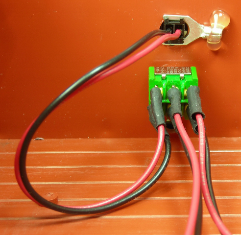
Spread the wings of the charging connector 90 degrees. Ensure the locking nub of the connector is facing up. Wiggle the base of the charging connector through its hole in the rear wall of the car body. Slide the prongs of a 1/4 inch spade connector across the base of the connector on the inside of the car body to hold it in place. Secure the spade bit with a dab of hot glue.
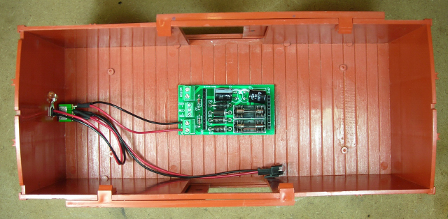
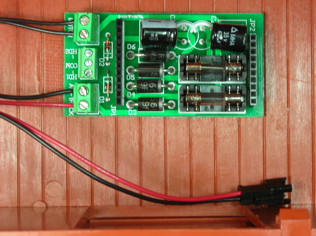
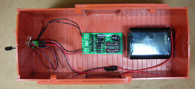
Fasten the Plug and Play Board to the center of the car floor with the screw terminals facing the switch in the front of the car as shown.
Strip a bit of insulation off the ends of the red and black wires soldered to the right terminals of the battery switch and tin them. Fasten them under the screw terminals labeled TRACK.
THE MU CONNECTOR
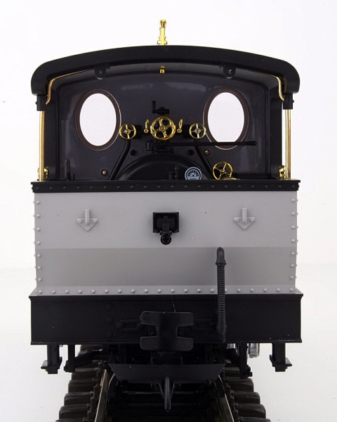
On the rear of the locomotive is a small, black cover over a 2-pin header that is normally used to power lighted cars. But in this project it will be used to power this locomotive with this trailing power and control car.
The female half of an All Electronics 2-wire connector set, as shown on the left, has the same connector as an Aristo-Craft, lithium-ion battery. It will be used as the MU connector between the power and control car and locomotive.
To make the connector fit in the power header on the locomotive however, the wings must be removed.
As the header is attached to the locomotive and can be covered when not in use, the connector will remain wired to the power and control car.
Trim the wires of the female connector to 8 inches in length. Strip a bit of insulation off the ends of the wires and tin them.
Pass the wires through the bottom hole on the front of the car, and fasten them under the screw terminals labeled MOTOR.
Measure 4 inches from the screws terminals, and place a blob of hot glue on the wires of the MU connector. This will act as stress relief should the locomotive and power and control car uncouple while hauling a train.
Ensure the battery switch is in the center-off position. Plug the battery into the connector soldered to the center terminals of the battery switch.
Install the Revolution receiver into the Plug and Play Board ensuring the pins on the receiver are properly seated in the socket.
Toggle the battery switch to the run position. To program the receiver follow the instructions in The Installation and Operation Manual for the Revolution Train Engineer that is on the CD that comes with the set. The Revised Manual and other information is also available on the Aristo-Craft web site as an Adobe pdf file. To read or download the revised manual, click on the link.
TESTING THE POWER AND CONTROL CAR
Snap the roof back on the car. The battery connectors and the linking button on the receiver can be accessed by opening the doors.
Place the locomotive and power and control car on a track or test stand. Remove the power cover from the rear of the locomotive, and plug in the MU connector. Toggle the battery switch to the run position.
Use the Revolution throttle to test the locomotive in both directions. You may have to use the ASSIGN FUNCTIONS menu to adjust the START SPEED to obtain a reasonable response time from a stop.
CONGRATULATIONS! You now have a power and control car and locomotive that will let you enjoy the benefits of battery power and radio control. ENJOY!
UPDATED APRIL 2012
The lights and sound boards in some LGB locomotives will not function properly if they are powered with the Pulse Width Control (PWC) output of the Revolution receiver. An experienced LGB enthusiast has also expressed a concern that the PWC output will cause LGB motors to overheat. Fortunately Aristo-Craft has released a PWC to Linear DC Board (CRE 57091) to fix this problem.
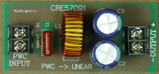
It converts the output from PWC back to linear DC. If installed in the output (MOTOR) wires of the Revolution receiver; the motors, lights, and smoke units would then behave exactly as they did with clean, linear DC, track power.
Remove the Plug and Play Board and the hot glue that held it to the boxcar floor.
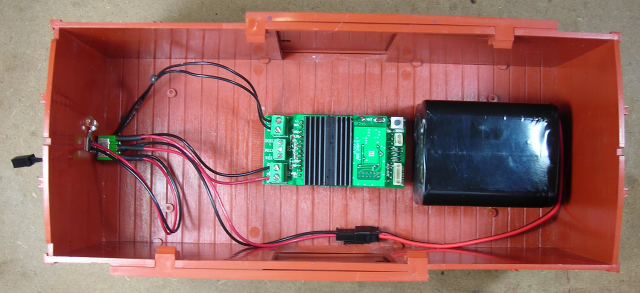
Fasten the PWC to Linear DC Board to the floor next to the door with hot glue with the output terminals towards the battery switch as shown.
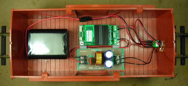
Fasten two nylon spacers beside the PWC to Linear DC Board. Fasten the Plug and Play Board and receiver to the floor beside the spacers.
Unfasten the MU connector wires from the MOTOR screw terminals on the Plug and Play Board, and fasten them under the OUTPUT screw terminals on the PWC to Linear DC Board. Polarity is not an issue as it will change with each change of direction.
Cut two wires to eight inches in length. Strip about 1/4 inch of insulation off both ends of the wires and tin them. Fasten one end of the wires under the MOTOR screw terminals of the Plug and Play Board. Pass the wires through the two nylon spacers, and fasten the other end under the INPUT screw terminals of the PWC to Linear DC Board. Polarity is not an issue as it will change with each change of direction.
NOTES
Although this power and control car was designed for a specific LGB locomotive, any car with the same components could be used to power and control any locomotive with an MU connector and the track power pick-ups turned off or removed.
The voltage regulators in most USA Trains and some LGB and Bachmann locomotives are not compatible with the PWC output of the Revolution receiver and the lights will not work. As most smoke units are powered by voltage regulators, they may not function either. Some older sound systems (Dallee, LGB, Sierra, etc.) will not function properly when powered with PWC. With a PWC to Linear DC Board installed in a power and control car however, all of these locomotives and sound boards will function exactly as they did with clean DC track power.