
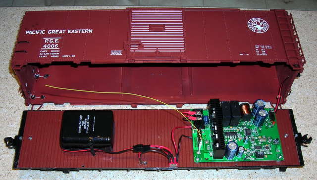
Aristo-Craft, Plug and Play locomotives have MU connectors on each end, and a switch to change between track power and battery power. This article details how to build a 40 foot, power boxcar to take advantage of those connectors. A power and control car is simply a battery car with a receiver added for on-board radio control.
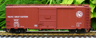
This power and control car utilizes only one, Aristo-Craft lithium-ion battery and is designed to power and control one small locomotive like a Pacific or GP-40.
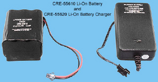
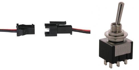
As this is an enclosed car, the battery will be charged on-board using a 2-wire connector. A Double Pole – Double Throw (DPDT), center-off switch will be used to toggle the battery between the charging connector and the receiver. The connector set and switch are both available from All Electronics under catalog numbers CON-240 and MTS-12 respectively. OVGRS members only can purchase the connector set and switch by contacting Paul Norton.
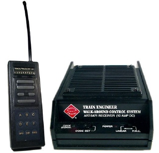
Although an Aristo-Craft, 27 MHz, Train Engineer (TE) set was used to provide the radio control for this project, a Revolution on-board or trackside receiver could be instead.
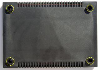
REMOVING THE CAR BODY
Remove the 6 long chrome screws indicated with yellow from the bottom of the car. Open the doors and remove the small screw from the bottom of each door frame.
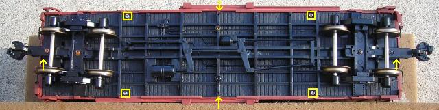
Lift the car body from the frame. If it sticks at the corners, use two, small flat screwdrivers to gently separate the car body from the frame at one end. Fasten the screws back in the frame and car body, so they do not get lost. Set the car body aside for now.
POWER AND CONTROL CAR SWITCH
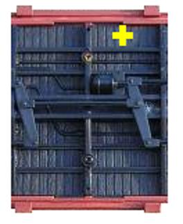
Drill a 1/4 inch hole in the frame at the spot marked with the yellow X for the Double Pole – Double Throw (DPDT), center-off switch.
Install the power and control car switch so it toggles toward the front and back of the car. Stick a CHARGE label on the front side of the switch and a RUN on the other as shown.
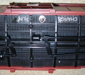
Check to ensure the switch is in the center off position.
BATTERY CHARGING CONNECTOR
CAUTION: The wire colours on the connector sets sold by All Electronics may not be positioned the same as the wire colours on the connectors of lithium-ion batteries and chargers. If not, click on the following link to see how to switch the positions of the AE Connector Set Wiring so that proper polarity is maintained.
The female half of an All Electronic connector set has the same connector as the Aristo-Craft, lithium-ion battery. Trim the wings off an AE female connector.
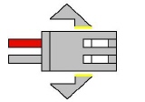
Drill a 5/16ths inch hole in the frame at the spot marked with the red X for the battery charging connector. Drop the wires of the connector through the hole. Spread the wings of the connector out, and wiggle the base through the hole. Slide a 1/4 inch spade terminal across the bottom connector to hold it in place. Secure the spade terminal with hot glue.
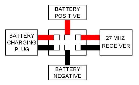
Flip the frame over and cut the connector wires to a length that will easily reach the power and control car switch. Slip a small length of shrink wrap over each of the wires, and solder them to the switch as shown in the following diagram. Slip the shrink wrap down and warm to seal the solder joints.
That completes the installation and wiring of the lithium-ion battery charging connector.
LITHIUM-ION BATTERY
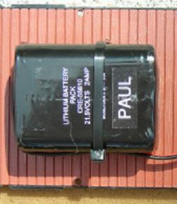
Drill two, 3/16th inch holes in the frame as shown in the following picture. Pass a long cable tie through the holes taking care not to damage the frame details.
Use a strip of double-sided tape to fasten the lithium-ion battery to the car floor between the two holes as shown. Secure the battery using the cable tie.
The male half of an All Electronics connector set has the same connector as the Aristo-Craft, lithium-ion battery charger. Solder and shrink wrap the wires of the male half of an AE connector set to the center tabs of the power and control car switch as shown in the following diagram.
Check to ensure the position of the wire colours on the AE connector and battery connector are matched before connecting the two of them.
That completes the installation and wiring of the lithium-ion battery.
27 MHZ TE RECEIVER
Turn the case of the TE receiver over and remove the four screws at the corners. Open the case and remove the circuit board. If it sticks, remove the fuse. As this is a light power and control car, it would be a good idea to replace the 10 amp fuse with a 5 amp fuse. Put the case back together, install the four screws, and put it back in the box it came in.
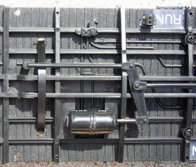
Place the circuit board or template in the front end of the frame as shown. Drill 3/32nd inch holes in the floor of the car using the holes in the corners of the receiver or template as a guide. Tap the holes with a 4-40 screw.
Under the receiver, glue 1/4 inch long spacers around the holes at each corner. The nylon spacers are available from All Electronics under catalog # SP-42. OVGRS members only can purchase the spacers by contacting Paul Norton.
Fasten the receiver to the floor of the car with 1/2 inch 4-40 screws.
Cut the heavy red and black power input wires of the receiver to a length that will easily reach the power and control car switch. Slip a small length of shrink wrap over the end of each wire. Solder the wires to the switch as shown in the following diagram. Slip the shrink wrap down and warm to seal the solder joints.
Check to see that all the red wires on the power and control car switch are soldered to one side and all the black wires to the other.
That completes the wiring of the power and control car switch.
ANTENNA UPDATE
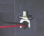
Initially the Azarr Micro-Lite antenna pictured above was used for this power and control car, but unlike the Evans power and control car the resulting radio range was very poor. Reversing the receiver so the antenna passes over it instead of the battery may provide better results, but I would recommend using the Aristo-Craft wire antenna instead. The installation of the antenna will be documented later.
CHARGING THE LITHIUM-ION BATTERY
If the lithium-ion battery has not been charged, plug the battery charger into the battery charging connector on the bottom of the frame. Plug the charger into a wall outlet and toggle the switch toward the front of the car. Check the battery voltage every hour. The voltage should be allowed to exceed 25.2 volts, and the battery should not remain on the charger for more than four hours. When complete, toggle the switch to the center off position and remove the charger.
PROGRAMMING THE 27 MHZ RECEIVER
The receiver has a small power switch next to the fuse. Turn it on by sliding it toward the heat sink. Slide the small switch on the back of the circuit board toward the red LED, its linear power position. If this switch is left in the PWC position, the momentum and soft reverse features will not work. The lights on some USA trains and Bachmann locomotives may not work properly with PWC, nor will some analog sound boards.
Programming momentum prevents sudden starts or stops which could damage the gears in a locomotive, especially if it is hauling a long train. The soft reverse feature can be used when switching cars. When the reverse button is pushed the locomotive will slow to a stop, pause while a car is coupled or uncoupled, change directions, and gradually resume speed in the other direction.
Toggle the power and control car switch on the bottom of the frame toward the back of the car to turn the receiver on. The red LED on the back of the circuit board should light up and stay on.
Link and program the transmitter and receiver as detailed in the Aristo-Craft manual that came with them. If the transmitter is used with other receivers, using the first two digits of the car number to program the frequency and channel numbers is an easy way to remember them.
After programming the TE, leave the small TE power switch on but return the power and control car switch on the bottom of the frame to the center off position. The red LED on the back of the circuit board should go out.
POWER AND CONTROL CAR CONNECTOR
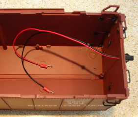
Drill a 1/8th inch hole in the center of the A end of the car body between the first two bottom ribs. Slip the wires of an All Electronics female connector through the hole in the end of the car body. The female connector has the same connector as the lithium-ion battery.
Hold the connector wires together and place a glob of hot glue on them about 2 inches inside from the car wall. This will act as stress relief should the power and control car and locomotive become uncoupled during operation. Two inches of slack in the connector wires however, does make it easier to connect the connector before the power and control car and locomotive are coupled together. The excess wire can be pushed back into the power and control car after coupling.
Some owners also remove the locking tab from the connectors on their locomotives. If the power and control car and locomotive become uncoupled during operation, the connectors will slip apart and the locomotive will stop. Alternatively, the ridge on the inexpensive power and control car connector could be filed flat and the locomotive connectors left untouched.
The wires should be long enough to pass under the receiver and reach the output screws on the receiver when the car body is set beside the frame. Strip 3/16ths of an inch of insulation off the end of the wires. Solder or crimp a number 6 stud, 18 to 22 AWG, loop terminal on each. The loop terminals are available from All Electronics under catalog number 8106.
Set the car body beside the frame. Slip the power and control car connector wires under the circuit board and fasten their loop terminals under the output screws on the receiver. This is the one time that polarity does not matter as it will change with each change of direction.
INSTALLING THE ANTENNA
As previously mentioned, initially the Azarr Micro-Lite antenna pictured above was used for this power and control car, but unlike the Evans power and control car the resulting radio range was very poor.
Fasten the Aristo-Craft wire antenna around the perimeter of the inside of the boxcar roof with hot glue. That completes the wiring of the power and control car.
REASSEMBLING THE CAR
Remove the two small screws from the frame and six long screws from the car body. Tuck any excess power connector wiring under the receiver. Place the car body back on the frame. Do not insert the screws yet.
Always ensure the power and control car switch is in its CENTER-OFF position before connecting or unplugging a locomotive. It is not unusual for a locomotive to jump slightly when the switch is toggled to power the receiver.
Connect the power and control car to a Plug and Play locomotive. Toggle the power and control car switch toward the rear of the car, and test the power and control car for function and range.
If you have a transmitter that has a dedicated button for each direction, you may find the arrows on the buttons and the direction of the train are mismatched. If so, just reverse the positions of the power and control car connector wires under the output screws of the receiver.
If everything functions properly, toggle the power and control car switch to the center off position, unplug the locomotive, and fasten the car body to the frame with the eight screws.
CONGRATULATIONS! You now have a power and control car that can let you enjoy all the benefits of battery power and radio control.