
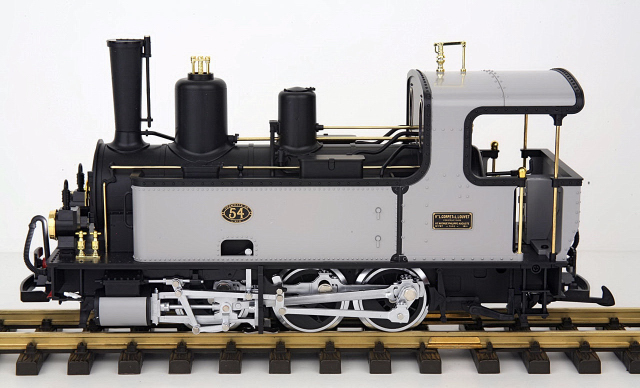
During the summer of 2011, I purchased this beautiful LGB 0-6-0 steam locomotive and a few European freight cars from the estate of a good friend Ralph Dipple.
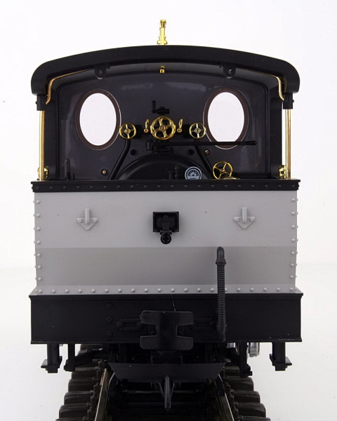
As a trailing power car will be used to battery power and radio control this locomotive an MU connector is required. Fortunately there is a power connector on the rear of the locomotive that can be used for just that purpose.
Removing the track power pick-ups is the only thing needed to prepare the locomotive for battery power and radio control. This is done to ensure the locomotive cannot pick up track power or feed battery power into the tracks. The result could be electronically catastrophic.
REMOVING THE TRACK POWER PICK-UPS
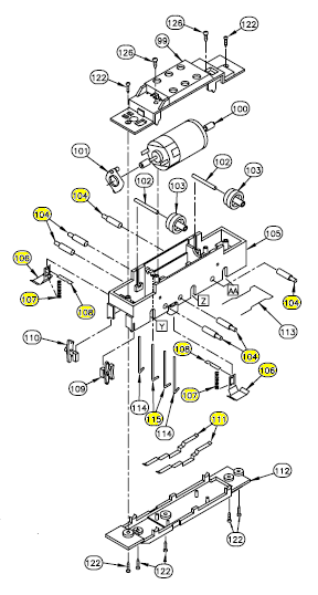
During the project several different parts will be removed from the locomotive. For clarity sake they will referenced by the page and part number in the Service Manual for this locomotive. The LGB 21780 Service Manual can be downloaded by clicking on the link. As the parts will be saved in a Ziploc bag, nothing prevents this locomotive from being restored to its original condition for re-sale at a later date.
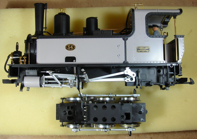
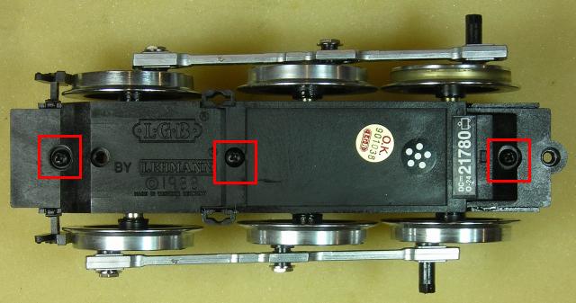
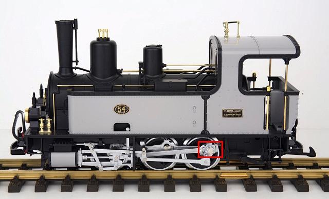
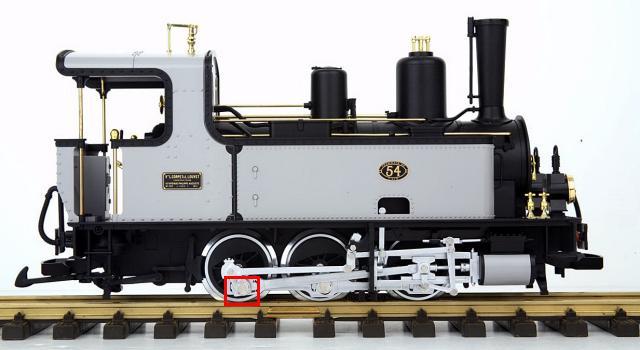
Remove the 1/4 inch (6.5 mm) bolt outlined in red from the drive rods on each side of the locomotive. Place them in a small container so they do not get lost.
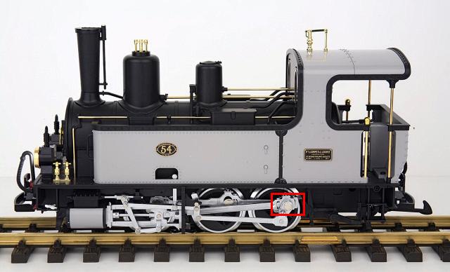
Lift the end of the rod for the reversing mechanism and the drive rod off the pin on the rear wheel on each side of the locomotive. Remove the washer off the pin on each side of the locomotive, and place them in a small container so they do not get lost.
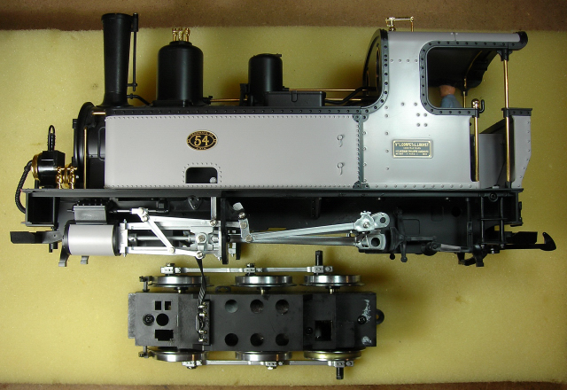
Usually I place a locomotive upside-down on a soft, engine work cradle to remove the track power pick-ups. But this particular locomotive has a fragile steam whistle on top of the cab roof, so it was placed on its side on a slab of foam instead. Do not try to remove the steam whistle, it is completely unnecessary and will probably break.
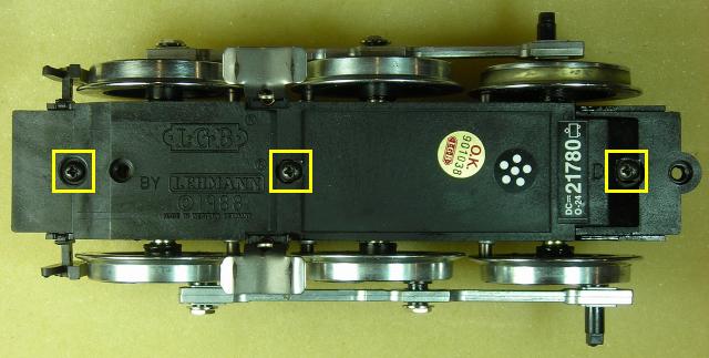
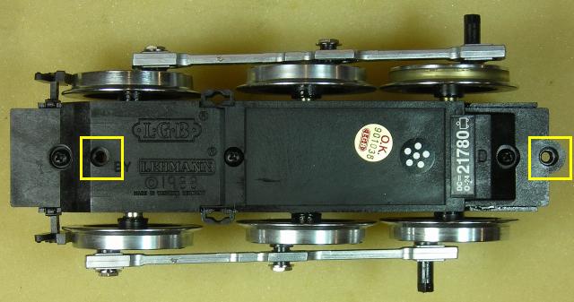
Remove the second and last screws, outlined in yellow, from the bottom of the motor block. Place them in the small container.
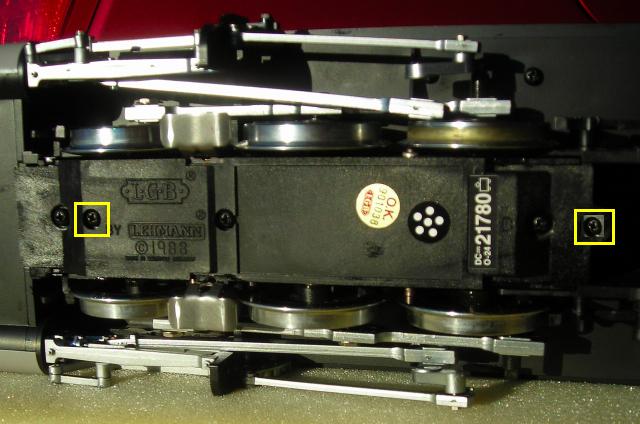
Slide the motor block out of the locomotive.
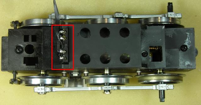
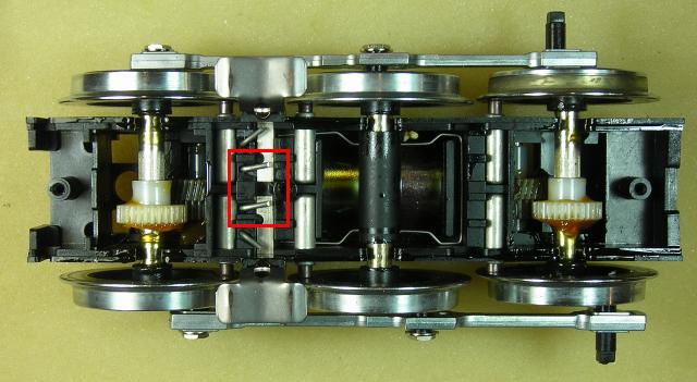
Pull the wiring connector, outlined in red, up out of the motor block. It is a firm fit. Set the locomotive aside for now.
Turn the motor block over and remove the first, third and fourth screws, outlined in yellow, from the bottom.
Remove the bottom of the motor block, and set it aside for now.
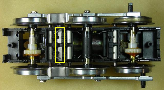
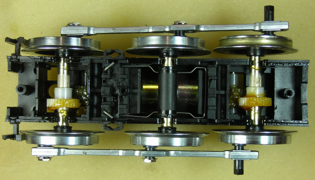
Lift the chrome jumpers (page 4, part number 21780-111), outlined in red, off the brush holders. Place them in a Ziploc bag labeled LGB 0-6-0 steam engine 21780.
Lift the brake shoes, outlined in yellow, out of the motor block case. Place them in the small container.
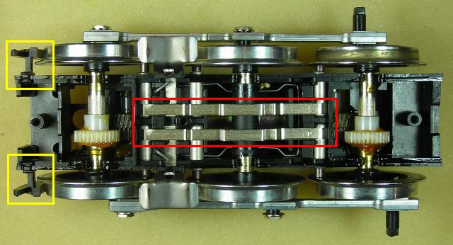
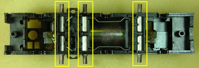
Pull the two metal power rods (page 4, part number 21780-115), outlined in red, out of the center of the motor block case. Place them in the Ziploc bag.
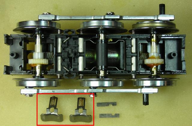
Push down on the track sliders to lift the ends of their metal securing bars, outlined in yellow, holding them in place. Remove the slider securing bars (page 4, part number 21780-108), and place them in the Ziploc bag.
Remove the track sliders and their springs (page 4, part numbers 21780-106 and 21780-108), outlined in red, and place them in the Ziploc bag.
Lift the axle sets and drive rods out of the motor block case. Remove the brushes (page 4, part 21780-104), outlined in yellow, and place them in the Ziploc bag.
Check to ensure the spring for the center axle is properly seated. Starting with the rear axle, place the axle sets and drive rods back in the motor block case. Check to ensure the gears on the front and rear axles are meshing with the gears in the motor block case. Each axle set should have a little bit of play, and the center axle should move freely up and down on its spring.
Install the brake shoes in the front end of the motor block case.
Before closing the motor block, check to ensure all the required track power parts have been removed and placed in the Ziploc bag.
2 power jumpers, part 21780-111
2 power rods, part 21780-115
2 slider securing bars, part 21780-108
2 track sliders, part 21780-106
2 slider springs, part 21780-107
6 brushes, part 21780-104
Place the bottom back on the motor block. Fasten three screws out of the small container in the first, third, and fourth holes outlined in red.
Turn the motor block over, and place the locomotive next to it on a slab of foam. Plug the connector into the top of the motor block.
Slide the motor block back in the bottom. Place two screws out of the small container in the second and last holes, outlined in yellow, and use them to fasten the motor block to the locomotive.
Using the next two pictures as a guide; place the washers, drive rods, and reversing mechanism rods back in place. Fasten them with the bolts out of the small container.
You should be able to turn all six wheels with the palm of your hand. The drive rods and valve gear should move freely without binding.
That completes the removal of the track power pick-ups.
POWER CONNECTOR
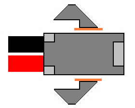
On the rear of the locomotive is a small, black cover over a 2-pin header that is normally used to power lighted cars. But in this project it will be used to power this locomotive with a trailing power car.
To make a suitable connector for the power header, the wings have to be removed from a two-wire female connector.
The 2-wire connector set is available from All Electronics under catalog # CON-240. OVGRS members can purchase the connector set by contacting Paul Norton.
As the header is attached to the locomotive and can be covered when not in use, the connector will remain wired to the power car. To read how the LGB Power and Control Boxcar was assembled, just click on the link.