
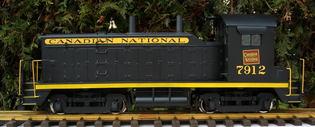
This project shows how to add an MU connector to the rear of a USA Trains NW-2 so you can use a trailing power and control car to run it. A power and control car is simply a battery car with a receiver added for on-board radio control.
Nothing in this project prevents this locomotive from being restored to its original condition for re-sale at a later date. As the track power wiring will be unplugged during this project, it will require a power and control car to run it. To view the articles on how to build a Power and Control Car, just click on the link.
REMOVING THE TRACK POWER SLIDERS
While it is not necessary to remove the track power sliders, they are redundant on a battery powered locomotive. Removing them will improve the appearance of the NW-2, provide a chance to lubricate the drive gears, and check the drive gear axle sleeves for splits.
Remove the handrails from both ends of the locomotive so they do not get bent or the stanchion bases broken. Place them in a small Ziploc bag, and set them aside for now.
Place the locomotive flat on its side on a slab of foam or cushioned engine cradle. Placing it upside-down may damage the horn and bell.
Remove the four screws and the bottom cover from each of the motor blocks. Place the screws in a small container so they do not get lost.
Remove the small screws from each track slider bracket. Lift out the track sliders, and the axle wipers sprung between the wheels.
The track sliders and axle wipers are the only components removed during this project. Wipe the grease off them, and place them in a small, plastic bag labeled with NW-2 along with the road name and number. Tape the bag in a pocket of the Styrofoam packaging so the components do not get lost.
Fasten the track slider brackets back in place with the small chrome screws.
Lift the axle sets out. If you can gently turn a wheel while holding the other, the axle sleeve on the drive gear is split. They can be fixed using the method in the DRIVE GEAR AXLE SLEEVES repair tip, or replaced with complete axle assemblies from USA Trains.
If required, lubricate the drive gears with plastic compatible grease. Place the axle assemblies back in the motor blocks. Ensure their bushings are seated flat [O] in the slots in the sides of the motors blocks. Ensure the worm gears on the motor shafts and the drive gears on the axles are properly meshed. The wheels should not turn.
Pop the covers back on and fasten them with their screws. Do not fully tighten any of the screws until all the screws have been inserted and turned down some. If you fully tighten the screws as you go, the last few may be hard to insert and may strip the threads in the plastic motor block.
OPENING THE LOCOMOTIVE
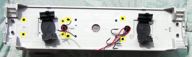
There are 8 screws in the bottom of the frame that hold the cab and hood to the frame.
In order to pivot the motor blocks sufficiently to reach some of them, it may be necessary to remove the couplers. Undo the small screw that holds each of the coupler centering springs to the frame. It is just under the motor block at each end of the frame.
Undo the screw holding each coupler to its bracket. Place the couplers, return springs, and small metal brackets in a small Ziploc bag; and set them aside for now. Fasten the screws back in the frame so they do not get lost or mixed up with others.
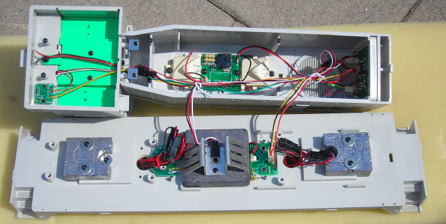
Remove the 8 screws that hold the cab and hood to the frame, and place them in the small container. Turn the locomotive right side up. Holding the back of the cab, carefully lift forward and up. The cab and hood will lift off as one piece. Do not lift it up too far or the wiring connectors may unplug. Set the cab and hood beside the frame.
Fasten the 8 screws back in the cab and hood so they do not get lost or mixed up with others.
Remove the two, white twist ties from the wiring, and place them in a small container.
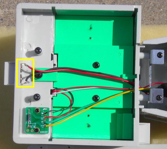
Unplug the 4-wire, white plastic connector from the small printed circuit board (PCB) in front of the weight in the center of the frame.
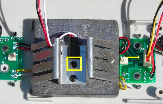
Undo the screw that holds the voltage regulator to the heat sink. Remove the voltage regulator and fasten the screw back in the heat sink so it does not get lost or mixed up with others.
Set the cab and hood aside for now.
DISCONNECTING THE TRACK POWER PICK-UPS
It is imperative that the track power pick-ups be disconnected so the locomotive cannot pick up track power or feed battery power into the tracks. The result could be electronically catastrophic.
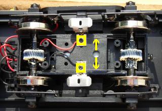
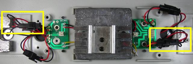
There are two sets of connectors attached to each motor block. But only one connector of each set has two red wires and two black wires attached to one side of it. These connectors provide the track power from the motor blocks to locomotive electronics. Unplug both of the 4-wire connectors to disconnect the track power.
THE MU CONNECTOR
The male half of a 2-wire connector set, shown on the right, will be used as the MU connector.
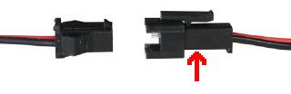
The 2-wire connector set is available from All Electronics under catalog # CON-240. OVGRS members can purchase the connector set by contacting Paul Norton.
Although the wires on the connector sets sold by All Electronics connectors may not positioned the same as on USA Trains connectors, there is no need to change the position of the wires over as the polarity will change with each change of direction of the locomotive.
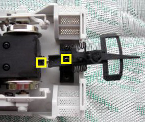
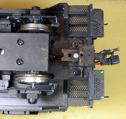
Drill a hole in the bottom of the frame just behind the rear motor block using a 1/8 inch bit.
Slip an inch of shrink wrap over the connector wires, and push it against the rear of the connector. With the locking tab of the connector facing up slip the wires through: the square on the rear pilot above the coupler, the coupler mounting bracket, and the hole drilled in the frame. The MU connector should extend over the coupler as shown.
I had originally planned to solder the MU connector wires the two solder tabs on the inside of the rear cab wall. However the two small receptacles are to be used for trailing car lights or sound only. The USA Trains on-line Manual for the NW-2 warns “Do not interconnect any two locomotives together using these receptacles or damage to one or both units will occur.”
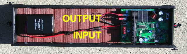
Instead a second male connector will be used to connect the MU connector wires directly to the printed circuit board behind the weight in the center of the frame. Plug the second male connector into a female connector soldered to the PCB that previously supplied the locomotive with track power.
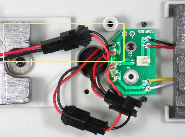
Trim the wires of the MU connector and the new male connector to a length that will allow them to be soldered together. Solder and shrink wrap the red wires together. Solder and shrink wrap the black wires together.
That completes the installation of the MU connector. The battery and radio control receiver in a trailing car can now power and control the speed and direction of the locomotive. All that is left to do is install the cab and hood, and test the locomotive.
RE-ASSEMBLING THE LOCOMOTIVE
Set the hood and cab together flat on a slab of foam or soft engine cradle, taking care not to damage the bell or horn. Place the frame next to them.
Plug the 4-wire, white plastic connector back into the small printed circuit board (PCB) in front of the weight in the center of the frame.
Use the screw in the heat sink to refasten the voltage regulator.
Gather the wiring using the two white twist ties in the small container.
Remove the 8 screws from the cab and hood and set them in a small container for now. Set the hood and cab back on the frame. Set the locomotive on a piece of track and connect a power and control car to test it.
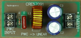
If the lights do not work, add a Crest Electronics PWC to Linear DC Board in the wires of the MU plug on the trailing power and control car. OVGRS members can purchase the PWC to Linear DC Board by contacting Paul Norton.
If the motors, lights, and smoke units function as they should; use the 8 screws to fasten the cab and hood to the frame.
Take the couplers from the small Ziploc bag and re-install them.
Re-install the railing to the front and back of the locomotive
Congratulations! You have successfully installed an MU connector on your USA Trains NW-2.
With a power and control car connected, you will now be able to enjoy all the benefits of battery power and radio control.