
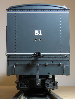
After adding an MU connector to an LGB Mallet, a power car was required to battery power and radio control the locomotive. The most suitable trailing power car for the Mallet was an LGB American tender.
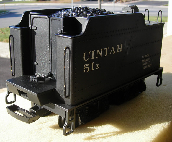
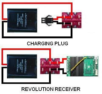
This power car was built by the late Ralph Dipple in the summer of 2011. He installed an Aristo-Craft lithium-ion battery and a Revolution receiver to provide the battery power and radio control.
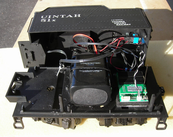
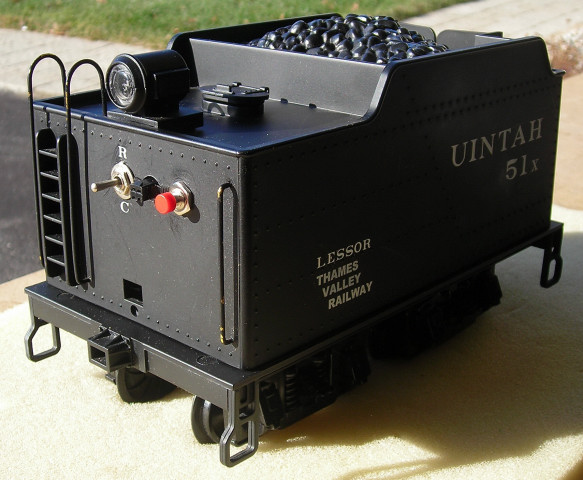
As it is an enclosed car, a connector is used to charge the battery. A switch is used to toggle the battery between the charging connector and the receiver. Ralph placed the switches and charging connector on the end of the car so they were easily accessible.
This article appears long because it detailed and includes a lot of pictures. But if you take your time and follow it step-by-step it is not difficult, and the results are well worthwhile.
Please read this article carefully highlighting the components that are needed. Sources of supply are suggested for items not sold by your hobby suppliers.
BATTERY SWITCH
Turn the tender over and place it on a soft surface. Remove the four screws outlined in yellow from the corners of the frame.
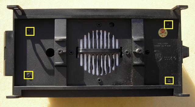
Turn the tender over and lift the car body from the frame. Fasten the screws in the car body so they do not get lost, and set the frame aside for now.
- Use a 1/4 inch bit to drill a hole in the back of the car body for the battery switch.
- Use a 5/16 inch bit to drill a hole for the charging connector.
- Use a 9/32 inch bit to drill a hole for the linking button.
As you have the drill out, you might as well drill a 5/32 inch hole for the four MU connector wires between the bottoms of the doors on the front of the tender.
Tape the floor in front of the doors, so the bit does not scratch the paint.
A Double-Pole Double-Throw (DPDT), center-off switch is used to toggle the battery between its charging connector and the adapter board for the receiver.
The switch is available from All Electronics under catalog # MTS-12. OVGRS members can purchase the switch by contacting Paul Norton.
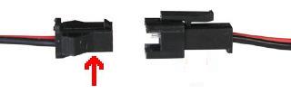
The male half of an All Electronics 2-pin connector set, shown on the right, has the same connector as an Aristo-Craft lithium-ion battery charger. It will be used to connect the battery to the center terminals of the switch.
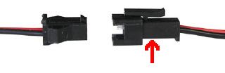
The 2-pin connector set is available from All Electronics under catalog # CON-240. OVGRS members can purchase the connector set by contacting Paul Norton.
CAUTION: The wire colours on the connector sets sold by All Electronics may not be positioned the same as the wire colours on the connectors of lithium-ion batteries and chargers.
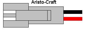
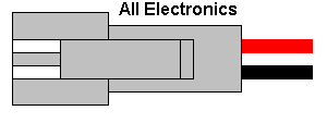
If not, click on the following link to see how to switch the positions of the AE Connector Set Wiring so that proper polarity is maintained.
As it is easier to solder and shrink wrap the wires to the terminals of the switch before it is installed; place the switch in a small bench vise with the terminals facing up.
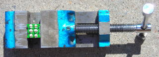
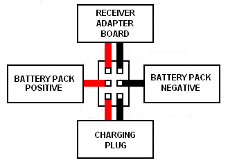
Solder and shrink wrap the wires of the male half of an AE connector set to the center terminals of the DPDT switch as shown in the following diagram.
CHARGING CONNECTOR
The female half of an All Electronics 2-pin connector set, as shown on the left, has the same connector as an Aristo-Craft, lithium-ion battery. It will be used as the battery charging connector.
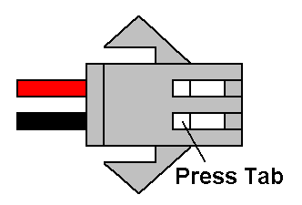
Push down on the small tabs on the back of the metal terminals of the female connector with a pin or hobby awl and gently push on the front of the terminals with a small screwdriver. After the terminals have moved, they can be withdrawn by pulling on their wires. Place the connector shell in a small container for now.
Solder and shrink wrap the wires of the female connector to the bottom terminals of the DPDT switch as shown in the following diagram.
Cut a one foot long length of red wire, and one foot long length of black wire. These will be used to connect the battery switch to the receiver adapter board. Solder and shrink wrap the wires to the top terminals of the DPDT switch as shown in the diagram above.
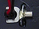
Install the DPDT switch in the rear wall of the tender with the wires for the receiver adapter board facing up and the wires for the charging connector facing down. The switch should toggle up and down. Stick a CHARGE label below the switch and a RUN label above it.
Pass the wires for the charging connector through the hole in the rear wall drilled for it. Check to see if the small tabs on the metal terminals are raised slightly. If not, use the blade of an X-Acto knife to do so. Push the metal terminal of the red wire into the back of the charging connector shell, ensuring it is in the same position in the shell as the red wire of the battery connector. Push the metal terminal of the black wire into the back of the charging connector shell. Test each wire to see they are locked into the connector.
Spread the wings of the charging connector. Wiggle the base of the charging connector through its hole in the rear wall of the car body, and slide the prongs of a 1/4 inch spade connector across the base on the inside of the car body to hold it in place. Secure the spade bit in place with a dab of hot glue.
REAR HEADLIGHT
In this power car the Revolution receiver was mounted at the rear of the frame using the adapter board that came with it. I removed the short coloured wires from the adapter board, but you can solder and shrink wrap the necessary wiring to them if you prefer.
OPTIONAL: A (non) Plug and Play Board could also been used instead of the adapter board. The screw terminals on the PnP Board eliminate the need to solder the wiring for the receiver.
Like the battery switch, it is easier to solder the wires to the adapter board before it is installed. The wires must be long enough so the car body can be placed next to the frame during assembly. If the rear headlight wires cannot easily reach the adapter board, solder and shrink extensions to them.
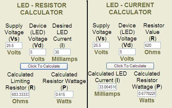
The Revolution receiver powers the lights directly from the lithium-ion battery which will should be charged to no more than 25.2 volts. Using the calculator on the Ngineering web site; it was found that a 680 ohm, 1 WATT resistor is required to drop the voltage for the light bulbs and handle the power of the circuit. Unfortunately my local electronics shop did not have that value of resistor; so 620 ohm, 1 WATT resistors were used instead. The headlamps do shine with a pleasant orange glow which would be prototypical for a locomotive of this vintage.
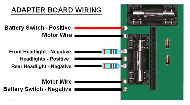
Push the lead of a 680 or 620 ohm, 1 WATT resistor through the hole in the solder pad labeled HD1 on the adapter board. This is the ground for the rear headlight. Solder the lead to the bottom of the board and trim the excess lead off flush.
Trim the lead on top of the resistor to about 3/8 of an inch long. Solder and shrink wrap one of the rear headlight wires to the shortened lead.
The remaining rear headlight wire will be dealt with in the following section.
FRONT HEADLIGHT
When the LGB Mallet was first tested with this power car; the locomotive was powered through a 2-wire MU connector set attached to the motor wires of the Revolution receiver. Although the motors and sound board functioned well, the headlight did not light until top speed. It is assumed, that like most USA Trains diesels, the voltage regulator that powers the front headlight is incompatible with the Pulse Width Control (PWC) output of the Revolution receiver. Two ways to correct the problem were discussed.
The first and simplest way would be to install an Aristo-Craft, PWC to Linear Board (CRE-57091) between the motor wires of the receiver adapter board and the wires of the power car MU connector. The motors, headlight, and sound would perform exactly as they did with linear DC track power. Unfortunately we did not have the required board.
The second method, as detailed in the LGB Mallet MU connector article, involves opening the locomotive, unplugging the front headlight wires, and extending them to a 4-wire connector on the back of the Mallet.
The four wires of the power car connector will be soldered to the Revolution receiver adapter board. The two motor wires from the adapter board will provide power through the connectors to the motors and the sound board. Another two wires from the adapter board will provide the power to the front headlight.
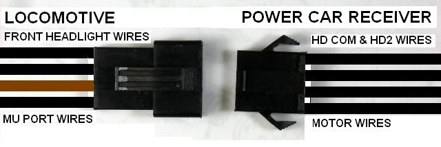
If the instructions in the Mallet article were followed, the brown and black wires from the Mallet MU connector ports will be on one side, and the two black wires for the lights will be on the other. When both MU connectors are plugged together, it can be determined which wires are for the front headlight.
With the notch on a female four-wire connector facing up, pass its four wires through the hole at the bottom of the doors in the front of the car body.
The 4-wire connector sets are available from All Electronics under catalog # CON-440. OVGRS members can purchase these connector sets by contacting Paul Norton.
If you have a D-sub crimper, you can change the colour of all the wires to black so they are less obvious. The female terminals required are available from coolight.com. OVGRS members can purchase the terminals by contacting Paul Norton.
Before soldering any of the wires to the adapter board however, ensure they are long enough to extend the MU connector about 4 inches beyond the assembled power car to make it easier to connect the locomotive and power car together. The excess wire can be pushed back into the power car after the locomotive has been coupled to it.
Push the lead of a 680 or 620 ohm, 1 WATT resistor through the hole in the solder pad labeled HD1 on the adapter board. This is the ground for the front headlight. Solder the lead to the bottom of the board and trim the excess lead off flush.
Trim the lead on top of the resistor to about 3/8 of an inch long. Solder and shrink wrap one of the front headlight wires from the MU connector to the shortened lead.
Solder the remaining front headlight wire from the MU connector and the remaining wire from the rear headlight to the solder pad on the adapter board labeled HD COM. This is the (positive) power for both headlights.
When operational, the appropriate headlight will come on full bright with the first push of the throttle button (1% power). The receiver will remove the ground of the headlight that is not supposed to be lit, depending on the direction of travel. The headlights and the direction of travel can be adjusted using a menu item on the throttle.
That completes the wiring of the headlights.
LITHIUM-ION BATTERY
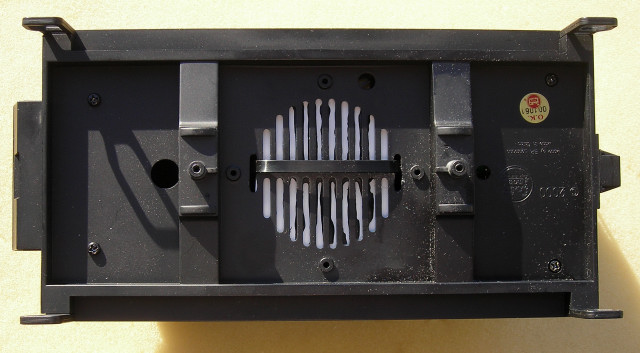
The lithium-ion battery was mounted over the speaker grill in the center of the frame. As there is ridge around the grill, a platform was made from 1/8 inch thick styrene to fit inside the grill and mount the battery flush with the top of the ridge.
I cut a 2 1/2 inch circle and trimmed the sides so the last slots on the side of the grill were not covered. But a rectangle of the proper proportions with its corners rounded may fit as well. Fasten the battery to the platform, as shown in the picture, with some double sided tape or Velcro.
Pass the open end of a cable tie down through one of the last slots in the speaker grill, across the bottom of the grill, and up the other side through the other slot. Fasten the tie around the battery snugly, but not enough to damage it as the double sided tape should keep the pack from moving. Trim the excess of the end of the tie.
Do not plug the battery into the connector on the battery switch at this time. That will be done when the all the wiring for the receiver adapter board is completed.
That completes the installation of the battery.
MOTOR WIRES
Solder the two remaining wires in the MU connector to the receiver adapter board at the solder tabs labeled MOR+ and MOT-. Polarity is not a concern as it changes with every change of direction.
Tightly fasten a small, cable tie around all four wires of the MU connector about four inches inside the front wall. Trim the end of the cable tie leaving a tag about one inch long. This will act as stress relief should the locomotive and power car become uncoupled.
That completes the installation of the MU connector.
REVOLUTION RECEIVER
Solder the red wire from the top of the battery switch to the solder tab on the receiver adapter board labeled TRK-. Solder the black wire from the top of the batter switch to the solder tab on the receiver adapter board labeled TRK+.
The Revolution receiver comes with its pins packaged in pink foam. Remove the foam and cut a 3/4 by 1 1/2 inch strip from it. Fasten some doubled-sided tape to the bottom of the foam strip. Push the rear 10 pins of the receiver into the top of the strip.
Push the 12 pins on the front of the receiver into the header on the adapter board. Fasten the receiver to the frame with the double-sided tape on the foam as shown in the following picture.
Fasten the adapter board to the frame with a dab of hot glue on the two corners.
Install the remote linking button in its hole in the back of the car body. Plug the connector into the back of the receiver.
Make sure the battery switch is in its center-off position. Plug the lithium-ion battery connector into the connector wired to the center of the battery switch.
That completes the installation of the electronics in the power car.
REASSEMBLING THE POWER CAR
Remove the four screws from the car body. Place the car body over the frame taking car no to pinch any wires. Turn the power car upside-down and place it on a soft surface. Fasten the four screws back on the corners of the frame.
Turn the power car back over. That completes the assembly of the power car.
TESTING THE POWER CAR
If the battery has not been charged, plug an Aristo-Craft lithium-ion battery charger into the charging connector on the back of the power car.
Toggle the battery switch down. A green LED on the charger should light up indicating the polarity of the wires is correct. Plug the charger into the wall.
Check the voltage of the battery every hour with a voltage meter. It should not be charged beyond 25.2 volts, or remain on the charger longer than 4 hours.
When the battery is fully charged, toggle the battery switch to its center-off position. Disconnect and unplug the charger.
Set the Mallet and the power car on the track or a set of testing rollers.
CAUTION: Always ensure the power car switch is in its center-off before connecting the power car to a locomotive.
Pull the wires of the power car MU connector out a few inches. Plug it into the MU connector on the locomotive. Coupler the power car to the Mallet and push any excess wire back into the power car.
To program the receiver follow the instructions in the Installation and Operation Manual for the Revolution Train Engineer on the CD that came with the set. The Revised Manual and other information is also available on the Aristo-Craft web site as an Adobe pdf file. To read or download the revised manual, click on the link.
Test the locomotive to make sure everything functions as it should. The headlights and the direction of travel can be adjusted using the ASSIGN FUNCTIONS menu on the throttle.
CONGRATULATIONS! You now have a power and control tender for your Mallet that can let you enjoy the benefits of battery power and radio control.