
Aristo-Craft diesels are sold with MU connectors on each end. This project shows how to add the same connector to the rear of a USA Trains SD70 so you can use a battery power and radio control trailing car to run it.
Nothing in this project prevents this locomotive from being restored to track power for re-sale at a later date. As the locomotive’s track power wiring will be unplugged during this project however, it will require a power and control car to run it. A power and control car is simply a battery car with a radio control receiver added for on-board radio control. To view articles on how to build Power and Control cars, just click on the link.
While this project deals with a specific locomotive, the principles may be the same for other USA Trains six axle diesels
REMOVING THE TRACK SLIDERS
Remove the railings from the sides and ends of the locomotive to prevent possible damage and set them aside for now.
Place the locomotive upside down in a soft cradle, taking special car to protect the three chime horns. Remove the small screws from each track slider bracket with a magnetic tipped screwdriver. Using needle nosed pliers, pull the track sliders towards the center of the motor blocks, so that the slot in the sliders clears the tabs on the bottom cover, and pull up.
Do not remove the bottom covers from the motor blocks unless you have lost one of the small screws or slider springs inside. If you have to remove them, stuff cardboard or foam between the top of the block and the frame to keep the motor blocks from dropping and dislodging the axles and their bushings. Unlike the axle bushings [O] in two axle motor blocks, the main axle bushings < O > in these blocks are rotated 90 degrees, tits up if you’ll pardon the expression. The smaller bushings [O] on the secondary shafts are not.
The track sliders are the only components removed during this project. They should be placed in a small Ziploc bag labeled with SD-70 along with the road name and number, and taped in a pocket of the locomotive’s Styrofoam packaging.
Fasten the track slider brackets back in place.
OPENING THE CAB AND LONG HOOD
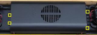
Remove the four screws from the base of the fuel tank. Remove the fuel tank and set aside for now. Install the fuel tank screws back in the frame so they don’t get lost.
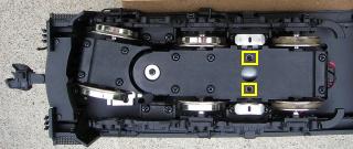
Under the cab there are two very small screws, highlighted in blue, in the side of the frame by the cab. A very small (2 or 2.4 mm) Phillips screwdriver will be required to remove them.
A six piece set of precision screwdrivers can be purchased from The Source in Canada (stock number 640-1962), Radio Shack in the USA (stock number 64-2969), and some dollar stores. The 3.8 mm screwdriver is my most used tool for large scale train work.
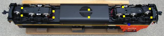
There are ten more screws, highlighted with yellow, holding the cab and hood to the frame. These are hidden in deep burrows in the frame and will require a long Phillips #1 screwdriver to remove them.
Do not remove the side frames or the motor blocks to access any of the screws, as the U-joint between the pivoting and main motor blocks may come undone. The U-joints can only be accessed by removing the top cover on the main motor block.
- The first two screws are directly behind the front pilot.
- The next two are hidden under the front truck. These are the hardest to remove. The truck will have to be turned and the screwdriver inserted between the side frames and the motor block between the center and rear wheels. The wheels may have to be pushed against the motor block for clearance.
- Two are in the middle of the empty area left by the fuel tank.
- Two are behind the fuel tank, in front of the rear truck.
- The last two are under the rear, pivoting motor block.
Turn the locomotive over. Carefully lift the shell from the rear. Do not lift the shell too far up or the front headlight wiring may unplug. The long hood and cab will lift off as one piece.
INSTALLING THE MU CONNECTOR
It is imperative that the track power pick-ups be disconnected so the locomotive cannot pick up track power or feed battery power into the tracks. The result could be electronically catastrophic
There should be two connectors from the front motor block, but only the connector has two red wires and two black wires attached to one side of it. This connector is for the front truck, track power pick-ups. The other is for the front motor.
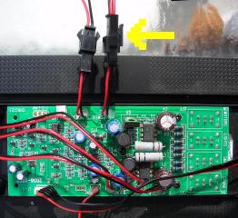
Undo the track power connector. This isolates the front truck, track power pick-ups and prevents battery power from being feed back into the tracks.
There should be two connectors for the rear motor block, but only one connector has two red wires and two black wires attached to one side of it. This connector is for the rear truck, track power pick-ups. The other is for the rear motor.
Undo the track power connector to isolate the rear truck, track power pick-ups.
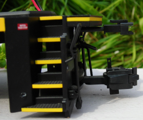
Drill a 1/8 inch hole in the center of the rear pilot above the cut bar and right under the anti-climber. Place a couple of pieces of masking tape on the anti-climber to protect it from the drill bit.
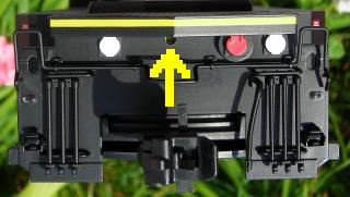
The hole should pass through the pilot and through the front wall of the box on the frame behind the pilot.
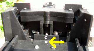
Drill a 1/8 inch hole through the frame in the center of the box behind the pilot.
Two, 2-wire connector sets are required for this project. They are available from All Electronics under part number CON-240. OVGRS members only can purchase them by contacting Paul Norton.
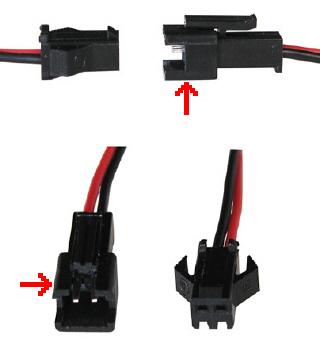
As only the male halves of two-pin connector sets indicated with red arrows are needed for this project. Unplug the female halves and set them aside. They can be used later for power and control cars and other projects. Hereafter the male halves of the sets will be referred to as an AE connector.
Although the All Electronics connectors may not wired the same as USA Trains connectors, there is no need to change the colour of the wires over as the polarity will change with each change of direction of the locomotive.
Slide a 3/4 inch length of shrink wrap over the wires of an AE connector until it reaches the back of the connector. With the tab of the connector facing up, feed the wires through the hole in the pilot over the coupler cut bar and through the hole in the wall of the box behind the pilot. Gently pull the wires until the shrink wrap is snug against the pilot. The connector should be able to move sideways without rubbing on the anti-climber. Now thread the wires through the hole in the center of the box on the frame.
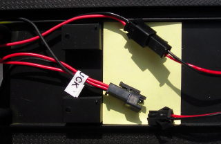
Insert another AE connector into the open connector that is attached to the power distribution board. This open connector used to carry track power from the rear motor block, but will now carry battery power from the rear MU connector.
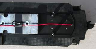
Gather the ends of the wires of the two AE connectors. Trim the wires to a useable length and strip 1/4 inch of insulation off all four wires. Slip a 3/4 inch length of shrink wrap over one of the red wires, and over one of the black wires. Solder the red wires together. Slip the shrink wrap down over the joint and warm it until it seals. Repeat for the black wire. Tape the wires to the rear weight.
That’s it! You have completed the installation of an MU connector or connectors on your USA Trains SD70. All that’s left to do is test to ensure the unit is wired correctly before re-installing the shell.
TESTING THE MU CONNECTOR(S)
Plug a power and control car into the MU connector on the rear pilot. If a power and control car is not available, connect the female portion of an All Electronics connector set to a small power pack for testing. Test to ensure the headlights and motors are both operating in the proper direction.
ASSEMBLING THE LOCOMOTIVE
Once the MU connector(s) have been tested; the shell, fuel tank and railings can be replaced. When installing the shell to the frame, all wires should be inside the mounting posts so they do not get pinched between shell and the lip of the frame.
CONGRATULATIONS! The MU connector will allow you to run your SD70 locomotive with a trailing power and control car and enjoy all the benefits of battery power and radio control.