
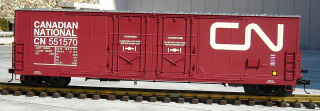
This article describes how to assemble an Evans power and control boxcar. This car will contain two lithium-ion batteries and a radio control receiver. When plugged into the back of an Aristo-Craft Plug and Play locomotive with the power switch set to battery power, the car can battery power and radio control it. It can also battery power and radio control other locomotives that have an MU plug added and the track power wires disconnected.
This power car is designed to power and control big diesels like a Dash 9 or SD-70 MAC. Although other types of batteries can be used, the lithium-ion pack is small, light, provides long run times, and holds its charge during winter storage.
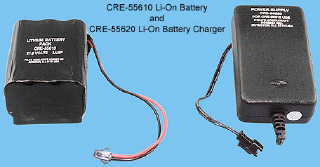
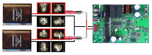
As this is an enclosed car, the batteries will be charged on-board using 2-wire connectors that mate with the Aristo-Craft battery chargers. One charger could be used, but two are recommended so that charging can be completed faster.
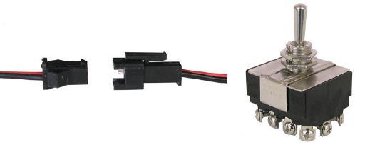
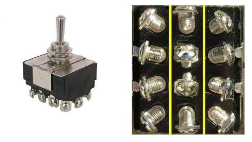
Unlike Gel Cell, Ni-Cad or NiMH batteries, Aristo-Craft lithium-ion packs must NOT be wired or charged in series. A standard, four-pole double-throw (4PDT) switch will be used to allow the packs to be connected in parallel to power the receiver, but charged separately.
The connector sets and switch are both available from All Electronics under catalog numbers CON-240 and STS-71 respectively. OVGRS members can purchase the connector sets and 4PDT switch by contacting Paul Norton.
An Aristo-Craft, 27 MHz Train Engineer (TE) set will be used to provide the radio control, as it can handle the power requirements of large diesels or multiple lash-ups. However a Revolution or Super Revolution receiver could be used instead.
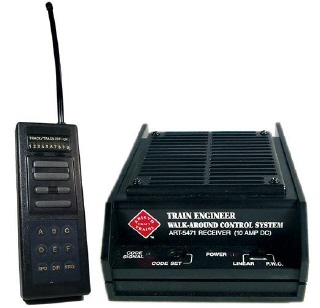
A boxcar is needed to provide the necessary height for the TE antenna.
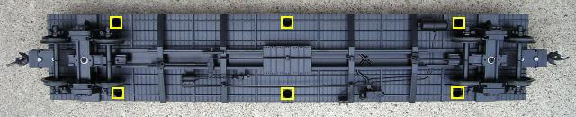
REMOVING THE CAR BODY
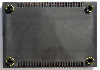
Remove the 6 screws indicated with yellow from the bottom of the car. Lift the car body from the frame. Fasten the screws back in the car body, so they do not get lost, and set it aside for now.
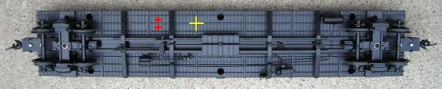
POWER CAR SWITCH
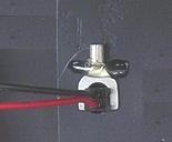
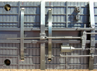
At the spot marked with the yellow X on the side of the frame WITHOUT the brake line, drill a hole with a 1/2 inch drill bit for the four-pole double-throw (4PDT) switch.
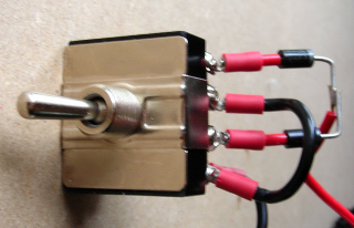
Install the power car switch so it toggles forward and rearward. Stick a Charge label on one side of the switch and a Run label on the other as shown.

Check to ensure the switch is in the center off position.
BATTERY CHARGING CONNECTORS
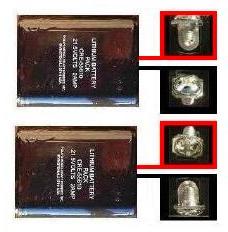
CAUTION: The wire colours on the connector sets sold by All Electronics may not be positioned the same as the wire colours on the connectors of lithium-ion batteries and chargers.
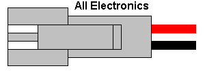
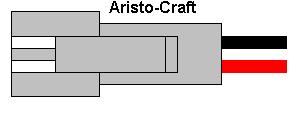
If not, click on the following link to see how to switch the positions of the AE Connector Set Wiring so that proper polarity is maintained.
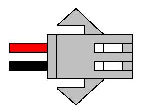
The female half of an All Electronic connector set has the same connector as the Aristo-Craft, lithium-ion battery.
At the spots on the frame marked with the red Xs, drill two holes with a 5/16ths inch drill bit for the battery charging connectors. Drop the wires of a connector through one of the holes. The wings of the connector are spread out, and then the base is wiggled through the hole. The base is held with a 1/4 inch spade terminal which is secured to the top of the floor with hot glue. Repeat the process for the other connector.
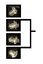
Cut the connector wires to a length that will easily reach the power car switch. Solder and shrink wrap a number 6 stud, loop terminal to the end of each wire.
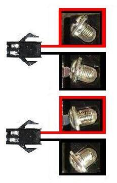
The 4PDT switch has 12 screw terminals. To make the wiring easier to understand the terminals have been divided into three columns: the left for the charging connectors, the center for the batteries, and the right for the TE receiver.
Fasten the charging connector loop terminals under screws in the LEFT COLUMN of switch terminals as shown in the following diagram. The colour coding of the wires from the center of the car to the edge should be: red, black, red, black.
That completes the installation and wiring of the lithium-ion battery charging connectors.
LITHIUM-ION BATTERIES
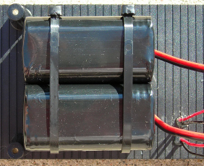
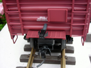
Drill four holes, with a 3/16th inch drill bit, in rear of the frame as shown in the following picture. Pass long cable ties through the holes taking care not to damage the frame details.
Use Velcro dots or double-sided tape to fasten the lithium-ion batteries between the four holes as shown. Secure the packs using the cable ties.
CAUTION: DO NOT CUT BOTH BATTERY WIRES AT THE SAME TIME. Take care when handling the battery wires to ensure they do not touch each other, or both make contact with any metal object such as a wire cutter, stripper, or screwdriver.
Cut the red wire of a battery about 1/4 of an inch from its plastic connector. Solder and shrink wrap a number 6 stud, loop terminal to the wire. Repeat the process for each of the other three battery wires one at a time.
Fasten the battery loop terminals under the screws in the CENTER COLUMN of switch terminals as shown in the following diagram. The colour coding of the wires from the center of the car to the edge should be: red, black, red, black.
That completes the installation and wiring of the lithium-ion batteries.
27 MHZ RECEIVER
Turn the case of the 27 MHz receiver over and remove the four screws at the corners. Open the case and remove the circuit board. If it sticks, remove the fuse. Put the case back together, install the four screws, and put it back in the box it came in.
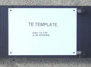
Place the circuit board or a TE template on the front end of the frame against the posts as shown. Drill 3/32 inch holes in the floor using the holes in the corners of the receiver or template as a guide. Tap the holes with a 4-40 screw.
Turn the receiver over and glue a 1/4 inch long spacer around the hole at each corner. The nylon spacers are available from All Electronics under catalog # SP-42. OVGRS members can purchase the spacers by contacting Paul Norton.
Fasten the receiver to the floor of the car with 1/2 inch 4-40 screws.
Fasten the Aristo-Craft wire antenna around the inside of the car roof with hot glue as close to the top as possible.
Cut the heavy, red and black, power input wires of the receiver to a length that will easily reach the power car switch. Solder and shrink wrap a number 6 stud, loop terminal to the black wire only.
Cut a piece about two inches long from the extra red and black wires cut from the receiver. Split the red and black wires apart, and set the small piece of red wire aside for now. Solder and shrink wrap a number 6 stud, loop terminal on each end of the black wire. This wire will act as jumper between two screw terminals on the switch.
Place the loop terminal on the black wire from the receiver and one of the loop terminals on the black jumper wire flat against each other. Fasten the loops under the screw in the RIGHT COLUMN of switch terminals as shown in the following diagram.
Fasten the loop terminal on the other end of the black jumper wire to the other switch terminal as shown. The switch can be moved 1/8 of a turn to access the screw behind the plastic post on the floor of the car.
Bend the terminals slightly outward so the black jumper and negative wire of the receiver are about 30 degrees away from the switch. This will make it easier to install the diodes in the next step.
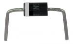
Two, 3 amp, 40 volt, Schottky diodes are a safety device to block power from passing from one battery to another. The power can only flow from batteries through the diodes to the receiver. The diodes are polarity sensitive and have a band around the end with the negative lead.
The diodes are available from All Electronics under catalog # 1N5822S. OVGRS members can purchase the diodes by contacting Paul Norton.
Straighten the positive leads of the two diodes. Strip a length of insulation off the small piece of red wire split from the black jumper. Cut two pieces exactly 7/16ths long from the insulation. Slip a piece of the insulation on the positive lead of each of the diodes.
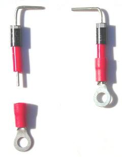
Slip a number 6 stud, loop terminal over the end of the positive lead of each the diode and solder them in place.
Fasten the loop terminals under the screws of the terminals in the RIGHT COLUMN of switch terminals so the negative leads of the diodes overlap as shown in the following diagram. The switch can be moved 1/8 of a turn to access the screw behind the plastic post on the floor of the car. Solder the red wire from receiver to the overlapping leads.
If you have a piece of insulation wide enough, cut a slot in it and press it over the top of the diodes and the receiver input positive wire. Alternatively, vinyl electrical tape could be used to cover the bare leads.
Check to ensure ALL the wires on the switch from the center of the car to the edge are colour coded: red, black, red, black.
That completes the wiring of the power car switch.
PROGRAMMING THE 27 MHZ RECEIVER
The receiver has a small power switch next to the fuse. Turn it on by sliding it toward the heat sink. Slide the small switch on the back of the circuit board toward the red LED, its linear power position. If this switch is left in the PWC position, the momentum and soft reverse features will not work.
Programming momentum prevents sudden starts or stops which could damage the gears in a heavy diesel, especially if it is hauling a long train. The soft reverse feature can be used when switching cars. When the reverse button is pushed the diesel will slow to a stop, pause while a car is coupled or uncoupled, change directions, and gradually resume speed in the other direction.
The lights on some Bachmann, LGB, and USA Trains locomotives will not work if the locomotives are powered with PWC. Some analog sound will also not work when powered with PWC.
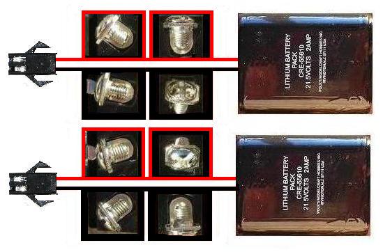
When the power car switch on the bottom of the frame is toggled rearward, the batteries are connected in parallel through the diodes and jumper wire to power the receiver.
Link and program the transmitter and receiver as detailed in the manual that came with them. If the transmitter is used with other receivers, using the first last digits of the power car road number to program the frequency and channel numbers is an easy way to remember them.
After programming the TE leave the small TE power switch on, but toggle the power car switch on the bottom of the frame to the center off position. The red LED on the back of the receiver board should go out.
CHARGING THE BATTERIES
If the batteries have not been charged, plug a charger into in each of the battery charging connectors. Plug the chargers into a wall outlet and toggle the switch forward. When the switch is toggled forward, each of the batteries is connected independently to its charger.
If an older Aristo-Craft charger without auto shut-off is being used, check the voltage of the batteries every hour. These batteries should not be charged to a voltage greater than 25.2 volts. Nor should they be left on a charger for more than four hours.
When charging is complete, toggle the switch to the center off position and remove the chargers.
POWER CAR CONNECTOR
Drill a 1/8th inch hole in the center of the front end of the car body between the first two bottom ribs. The front end of the car has no brake wheel. Slide a 1/2 inch length of shrink wrap down the wires of the female half of an AE connector set until it is against the connector. Slip the wires through the hole and pull them until the shrink wrap and connector are snug.
About 2 inches inside from the car wall, hold the wires of the connector together and place a glob of hot glue on them. This will act as stress relief should the power car and locomotive become uncoupled during operation. Two inches of slack in the connector wires however, does make it easier to connect the connector before the power car and diesel are coupled together. The excess wire can be pushed back into the power car after coupling.
Some owners also remove the locking tab from the connectors on their locomotives. If the power car and locomotive become uncoupled during operation, the connectors will slip apart and the locomotive will stop. Alternatively, the ridge on the inexpensive power car connector could be filed flat and the locomotive connectors left untouched.
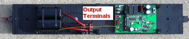
Solder and shrink wrap a length of wire to each of the power car connector wires. The wires should be long enough to pass under the receiver and easily reach the output screws on the receiver when the car body is set beside the frame.
Set the car body beside the frame. Slip the wires of the power car connector under the circuit board. Solder and shrink wrap a number 6 stud, loop terminal to the end of each of the wires. Fasten the loop terminals under the output screws on the receiver. This is the one time that polarity does not matter as it will change with each change of direction.
That completes the wiring of the power car.
REASSEMBLING THE CAR
Remove the six screws from the car body. Tuck any excess power connector wiring under the receiver and place the car body back on the frame. Do not insert the screws yet.
Always ensure the power car switch is in the CENTER OFF position before connecting or unplugging a diesel. It is not unusual for a diesel to jump slightly when the power car switch is toggled to power the receiver.
Connect a Plug and Play diesel or a diesel with an MU plug added and the track power wiring disconnected to the power car. Toggle the power car switch rearward, and test the power car for function and range.
If you have a transmitter that has a dedicated button for each direction, you may find the arrows on the buttons and the direction of the diesel are mismatched. If so, just reverse the positions of the power car connector wires under the output screws of the receiver.
If everything functions properly, toggle the power car switch to the center off position, unplug the diesel, and fasten the car body to the frame with the six screws.
CONGRATULATIONS! You now have an Evans power and control boxcar that lets you battery power and radio control a diesel or two. ENJOY!