
This article illustrates how Doug Matheson built steel through truss bridges for his Northland Railway.
I am lucky enough to have access to some metal working equipment. Admittedly metal working tools are not found in every workshop, however, the availability of inexpensive welding equipment from discount stores has now made metal working possible for many do it yourselfers. Having seen many fine bridges built by others, I decided to design and construct an eight foot through truss bridges made of mild steel.
I am not a machinist, nor have I been trained in metal working techniques. Accordingly, the discussion will focus on the results, and I will assume that anyone who has the gear will not need any pointers from an amateur like me on the how to of metal working.
BRIDGE DESIGN
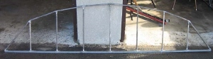
I wanted a modern looking, welded not just riveted, through truss bridge. The space in my garden needed a span of about 24 feet, so I somewhat arbitrarily broke it into three 8 foot spans. After my two visits to Marty Cozad’s North Table Creek Garden RR in Nebraska, I felt as though I had gone to the Cozad Design School. His objective is to capture the look and feel for such a bridge, making it strong enough to withstand any garden railroad use, while not necessarily modeling every fine detail. I liked the proportions of Marty’s, Bang’s Canyon bridge; shown in the following picture.
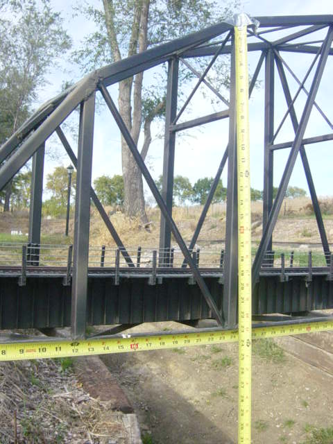
An eight foot long, through truss side was drawn with the 7 vertical beams on 12 inch centers. As a deck truss about 1 1/2 inches thick to hold the tracks was planned, a minimum of 13 inches of clearance was needed to allow 11 inches for the train. Therefore the first of the vertical beams on each end of the bridge had to be 13 inches high. I arbitrarily worked the proportions of the remaining vertical beams in an elliptical shape and they became 18 and 21 inches, with a middle beam of 22 inches.
The bridge was designed to be 9 inches wide inside to allow for extra long bridge ties to be used and a walkway to be built on either side of the track.
EQUIPMENT USED
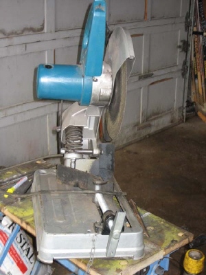
Mild steel is easily cut with a cut off saw.
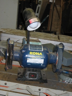
Then each piece of cut steel must be ground on a bench grinder to clean the sharp metal burrs around the cut.
Welding was done with a wire feed MIG welder.

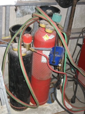
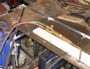
An oxyacetylene torch is very handy for heating joints and shaping steel.
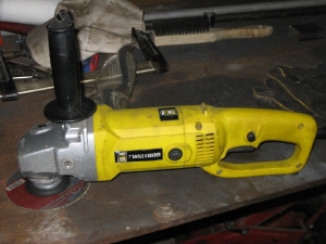
Final cleanup of welds is done with a 5 1/2 inch angle grinder or an air driven die grinder.
Safety around all power equipment is essential and is doubly so with steel. Steel when worked is very hot and has razor sharp edges. Heavy leather gloves are necessities. Similarly burning chips of metal are thrown everywhere so safety glasses, a head covering and heavy clothing should always be worn. A proper welder’s helmet must be used and no one should look into the white hot flame of the welder. That is enough said; common sense should prevail.
CONSTRUCTION
I journeyed over to Cohen’s steel yard and picked up 3/4 inch mild steel angle iron for the base beams on each side, 1/2 inch mild steel square tube for most of the bridge structure, and 1/4 inch mild steel rod for diagonal bracing.
Although parts were cut for both sides of the bridge, bench space limited the construction to one side at a time.
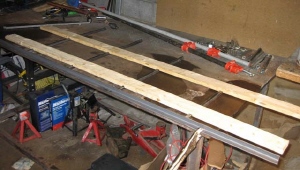
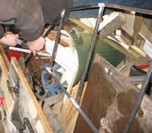
A piece of 3/4 inch angle iron was clamped flat on a steel workbench with the top side of the angle facing up. One foot centers for the vertical beams were carefully marked on the top side of the angle iron.
The vertical beams were cut in pairs with a chop saw from the 1/2 inch tube. The bottoms of the beams were set flush against the top of the angle iron. To hold the vertical beams straight, 1/2 inch slots were cut on 1 foot centers across two, 8 foot long pieces of 1 x 3 spruce boards. The two pieces of spruce were then placed on top of the vertical beams.
Although the bottom of each vertical beam is square, each pair has a different length and slightly different angle on top. The angle was obtained by setting a piece of 1/2 inch tube across the top of each pair and marking it. Each pair was then removed and cut to the proper angle with a chop saw. After being cut, the vertical beams were placed back in their original position and welded flush to the bottom of the angle iron.
The top girder was formed from a 10 foot long piece of 1/2 inch steel tubing. It was placed across the angle iron base at one end of the bridge and across the first vertical beam. The angle at the base was marked and cut with the chop saw. The top girder was then welded into place at the base and then at the top of the first vertical beam.
The tube was then heated with an oxy acetylene torch at the top of the first vertical beam and carefully bent to shape to run to the next upright beam where it was welded.
This process was repeated until the other end of the bridge was reached. Here the angle at the base was cut in place using an air driven Sawzall.
The tube was then welded to the base completing the installation of the top girder.
Next, the W bracing was cut and cleaned on the grinder to make a press fit on the bridge. Once all the braces were pressed in place, the joints were welded front and back. The rough welds were ground clean and smooth using an electric angle grinder with a 5 1/2 inch disc. The first side of the bridge was complete.
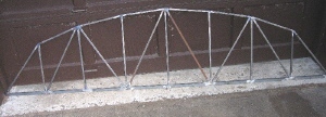
The process was repeated for the second side. When both were done; the basic bridge structure was to be completed by installing the cross pieces and associated bracing between the two.
A total of 12 cross pieces of 1/2 inch steel tube were cut to 9 inches in length. The sides of the bridge were placed upright, and 7 of the cross pieces were welded between the top girders at the top of the 7 vertical beams. Using the two end cross pieces as a guide, a mark was made on each the 5 middle vertical uprights on both ides of the bridge. The remaining 5 cross pieces were then welded to the middle vertical beams on the marks.
Nine more cross pieces were then cut 9 1/2 inches long. These were welded to the bottom of the angle iron on 12 inch centers to join the bottom of the bridge together.
Ten pieces of diagonal bracing were cut from 1/4 inch solid rod. They were ground down to press fit between the top cross pieces of the middle 5 pair of vertical beams, and then welded in place.
Similarly 4 more pieces of 1/4 inch rod were cut and welded in place between the top girders and first two cross pieces at each end of the bridge.
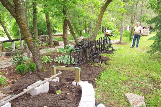
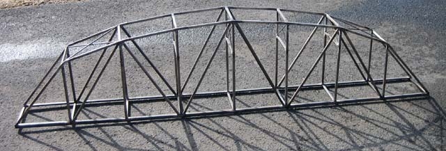
A laser level was used to survey the area where the bridges were to be installed. This allowed an accurate determination of the height of the steel towers to be built to support the bridges. Since the two ends of the total span are fixed, I needed two towers between the bridges for support. These were built of mild steel in the same manner as the bridge.
The only tricky part of the construction of the towers relates to the taper of the sides. They slope in at 10 degrees. I built 2 jigs for the sides (opposite sides are alike but adjacent sides are not) as shown in the photo.
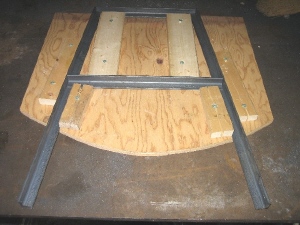
After each individual side was welded, the 4 sides were clamped together and welded. It should be noted that one tower was a couple of inches higher than the other – this extra was simply added to the lower part of the structure. The finished towers were sandblasted and painted black to match the bridge.
To install the bridges, the track at each end was terminated on a substantial “pier” formed of 2 4×4 posts set in concrete deck blocks with a crosspiece of 2×6 to take the bridge. The towers between bridges were set on patio stones set in turn on 6 inches of stone dust. The bridges were bolted into place securely.
Prototype bridges use a small deck truss to spread the load of the train along the full structure. To simulate this, a very straight white cedar 2×4 8 feet long was selected for each bridge and painted black. Given that the bridge will not occupy a foreground place in my garden, I opted to forego hand laid ties and track and simply use commercial track. I did however want walkways down each side of the bridge. Definitely, if the bridge is available for close up viewing, some extra detail on the deck truss and on the ties will go a long way to making a finer model.
I cut and stained 25 walkway carrying beams for each bridge. These beams were cut from clear white cedar and made 1/2×1/2×8 inches. Each of the 8 foot cedar 2×4’s was milled to give 1/2×1/2 slots every 4 inches the full length of the board. The slots permit the carrying beams for the walkways to sit beneath the commercial track. These slots were treated with Pentox to prevent rot before the carrying beams were air nailed into them. Now commercial track was laid (I used Llagas Creek code 215 with narrow gauge ties) the length of the 2×4 centered on the beams. Lastly, strips of clear cedar ½ inch thick were laid from the ends of the ties to the outside of the walkway carrying beams to finish the bridge deck.
The decks were installed on each bridge to complete the project. In the picture, the deck trusses can be clearly seen along with the track (and the lack of fine detail like guardrails!).
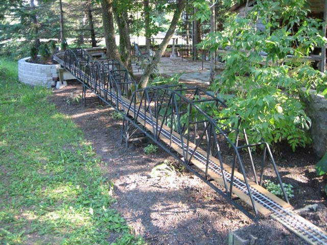
Some landscaping around the bridges in the garden and the three spans were ready for revenue service.
2 comments
Just wanted to comment on how great Doug Matheson’s bridge looks! Great job! I bet the trains sound pretty realistic as they cross!
Hi Danny!
There is a movie on the Video page showing trains running across those bridges.
Paul