
27 August 2020
Be aware that some of the USA Trains locomotive project articles that I posted years ago are somewhat out of date. The Crest Revolution receivers at that time all had Pulse Width Control for the output power. The voltage spikes in PWC would not let the light bulbs work properly in some USAT diesels. As I result I removed the USAT main circuit board and headlight circuit boards and replaced the headlight and number board lights with LEDs.
Precision RC now makes DC Linear Revolution receivers, so you no longer have to remove the main circuit board and change the lights in USAT diesels. Some of the new USAT diesels also have LED lights that work with the Revolution PWC receivers.
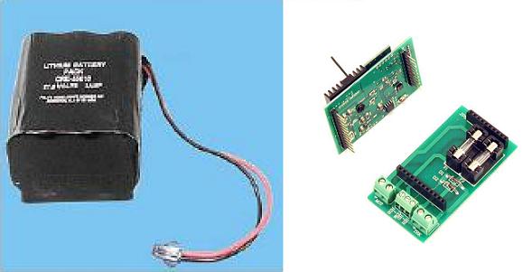
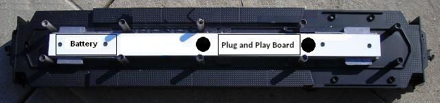
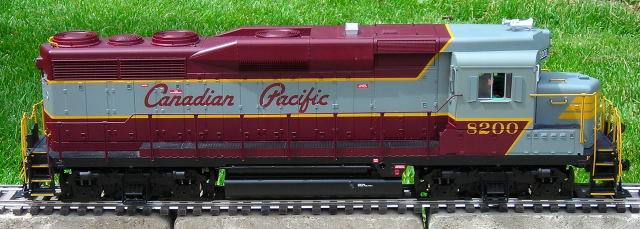
This article details a method used to convert a USA Trains GP-30 diesel from track power to on board, battery power and radio control using an Aristo-Craft, lithium-ion battery and a Revolution receiver in a Plug and Play Board.
The battery switch and receiver will control all the functions of the battery, charging connector, motors, and lights; making the USA Trains main printed circuit board with its four switches redundant. The voltage regulators on that board that drive the incandescent lamps are also incompatible with the Pulse Width Control output of the Revolution receiver. As the factory lighting circuit boards would not function properly, even if the main printed circuit board was retained, they will be replaced with LED headlights and number board lights.
The number board LEDS will light as soon as the battery switch is turned on. The headlight LEDs will come on with the first push of the Revolution throttle (1% power) long before the motors start to move. Although LEDs are much brighter than the factory bulbs, they will draw a fraction of the power and extend battery run times. The locomotive will also start sooner and run smoother at low speeds.
If the smoke unit is to be retained, an Aristo-Craft, Smoke Unit Control Board will also be required.
As the redundant factory electronics will be stored intact in a large Ziploc bag, nothing prevents the locomotive from being restored to its original condition for re-sale at a later date.
Please read this article carefully, highlighting the components that are needed. Sources of supply are suggested for items not sold by your hobby suppliers. OVGRS members can purchase the required components by contacting Paul Norton.
The article appears long because it detailed and includes a lot of pictures. But if you take your time and follow it step-by-step it is not difficult, and the results will be well worthwhile. Although a GP-30 was used for this installation, the instructions could be used to re-power other USA Trains, 4-axle diesels.
REMOVING THE SHELL
Using a small flat screwdriver, gently pry the handrail stanchion tabs from their holes in the frame. Set the handrails from the sides and ends of the locomotive aside for now.
Place the locomotive upside down on a soft cradle taking care not to damage the horns. Remove the leaf spring stirrups from the side frames. Remove the screws outlined in yellow, and slip the side frames from the ends of the wheel axles.
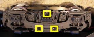
Unplug the four wires from each of the motor blocks. Wipe the excess grease off the ends of the axles, and set the motor blocks aside for now.
It is imperative that the track power wiring be removed to ensure the locomotive cannot pick up track power or feed battery power into the tracks. The result could be electronically catastrophic. Unsolder all the wires from the tabs on the inside of all the side frames. Wipe the grease off the wires that ran between the tabs, and place them in a large Ziploc bag labeled GP-30 along with the road name and number.
Wipe the excess grease off the side frames. Re-install them and their leaf spring stirrups.
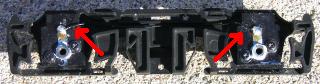
Remove the four screws that hold the fuel tank to the frame. Remove the tank. Fasten the four screws back in the frame so they do not get lost or mixed up with others.
Remove the screws indicated with the yellow arrows, and place the brackets and couplers in the fuel tank. Set the fuel tank aside for now. Fasten the four screws back in the frame so they do not get lost or mixed up with others.
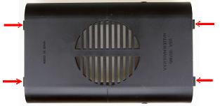
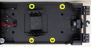
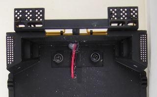
Remove the four screws outlined with yellow that hold the battery boxes to the frame. Place them in a small container for now.
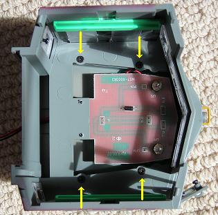
There are ten screws indicated with yellow arrows that hold the shell to the frame. These are hidden in deep burrows and will require a long, number 1 Phillips screwdriver to remove them.
Four are in the front motor block area.
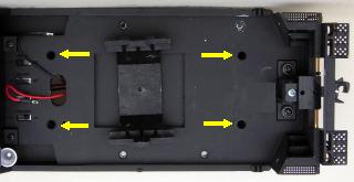
Two are in the fuel tank area.
Four are in the rear motor block area.
Remove these 10 screws and place them in the small container with the others.
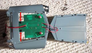
Turn the locomotive over and set it beside the engine cradle. Holding the ends of the shell, carefully lift it straight up. The whole shell (long hood, cab, battery boxes and short hood) will lift off as one piece. Set the shell on the engine cradle beside the frame. Fasten the screws in the small container back in the shell so they do not get lost or mixed up with others.
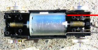
REMOVING THE FACTORY ELECTRONICS FROM THE FRAME
Remove the two, white twist ties from the wiring.
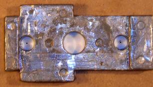
Pull the disconnected motor block wires through the holes in the frame. Remove the screw that holds each of the voltage regulators to a weight. Remove the voltage regulators, and fasten the screws back in place.
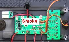
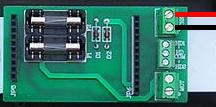
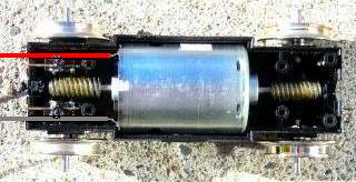
Unplug the connector on the T-shaped printed circuit board (PCB) for the smoke unit. Remove the four screws holding the T-shaped PCB and the small one behind it to the frame. Remove the PCBs and place them in the Ziploc bag. Fasten the four screws back in place.
That completes the removal of the factory electronics from the frame.
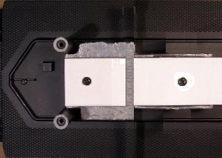
THE COMPONENTS PLATFORM
A platform will be made from two pieces of 1/8 inch thick styrene to mount the Aristo-Craft, lithium-ion battery and Plug and Play Board.
Remove the screws and washers from the weights and place them in a small container. Measure accurately the length from the outside end of one weight to the outside end of the other.
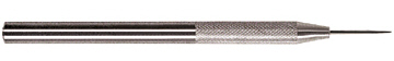
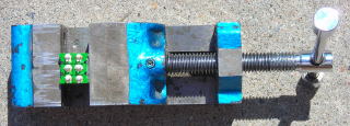
Score and snap two strips of styrene 1 3/16 inches wide by the measured length. A hobby awl made by Excel is an excellent and safe tool for scoring styrene. Once the awl has been used, an X-Acto knife will be less likely to wander. The styrene will have to be scored on both sides to snap cleanly.
If you place a dot on one end of the styrene strips and the rear weight, it is easier to place them correctly during the assembly of the components platform.
Remove the weights and securely tape one to each end of a styrene strip. Hockey shin pad tape is great for this as it stretches somewhat, sticks well, and will not leave glue behind. Ensure that each end of the strip is flush with the ends of the weights.
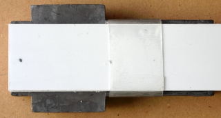
Turn the weights and styrene strip over. Insert an 11/32 inch drill bit in each of the holes in the ends of the weights. Turn the drill bit with your fingers to make a circular mark in the styrene sheet.
Remove the tape and the styrene strip from the weights. Place the weights back on their mounting posts.
Tape both pieces of styrene together ensuring the edges and ends are flush, and the marks made with the drill bit are facing out. Using the marks as a guide, drill four holes through both pieces with a 1/8 inch bit. Remove the tape and separate the strips.
Use the four screws to fasten one of the strips to the top of the weights. If it does not fit properly, try turning it around or flipping it over. Place marks on the strip 1 1/2 and 1 3/4 inches from the end of the long hood weight.
Remove the strip, and use the farthest mark to score and snap a 1 3/4 inch long piece off the strip. Use the second mark to trim the small piece to 1 1/2 inches long. Place the two pieces back on the weights, making sure the ends of both pieces are flush with the ends of the weights. The slot between them will be for the cable tie to secure the lithium-ion battery to the components platform.
Take the unmodified styrene strip and enlarge the four holes in it with a 1/4 inch drill bit. These holes will pocket the heads of the four screws holding the weights to the frame. The pockets will prevent the screws from damaging the bottom of the battery.
Test fit the second strip over the two lower pieces making sure the edges and ends are flush and the holes line up. Glue the second strip to the two lower pieces. I tried several glues and found that Testors plastic cement was the easiest to use and held the pieces together well. Use the screws and washers to hold it in place while the glue dries.
When the glue has dried, place a ruler across the front of the posts behind the cab and draw a line across the platform. Place the ruler in front of the next pair of posts and draw a second line across the platform.
Remove the platform from the frame. Measure to the center point of each line and place a mark. Drill a hole using a 3/4 inch spade bit at each of the marks. Smooth any sharp edges around the holes with fine sandpaper. These holes will be used to feed wires from the motors and battery switch.
Fasten the platform back on the weights with the screws. Place the washers in the Ziploc bag. That completes the assembly and installation of the components platform.
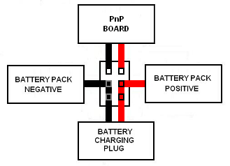
THE BATTERY CHARGING CONNECTOR
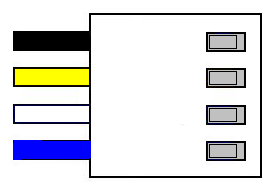
The female half of an All Electronics, 2-pin connector set shown on the left will be used as a charging connector for the on-board battery. The connector set is available from All Electronics under catalog numbers CON-240.
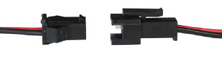
CAUTION: The wires on the connector sets sold by All Electronics may not be positioned the same as the wires on the connectors of lithium-ion batteries and chargers. If not, click on the following link to see how to switch the positions of the AE Connector Set Wiring so that proper polarity is maintained.
To make the charging connector inconspicuous, trim the wings off and sand the sides smooth.
Drill a hole in the rear pilot in the middle of the coupler cut bar using a 1/8 inch bit.
With the ridge on the battery charging connector facing up, feed the wires through the hole in the pilot. Gently pull the wires until the connector is snug against the pilot.
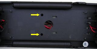
Flip the frame over and drill a hole in the frame opposite the screw for the coupler centering spring using a 1/8 inch drill bit. Feed the wires through the hole in frame, and route them inside the frame posts alongside the components platform.
Add a dab of hot glue to the wires behind the pilot to keep them in place and hold the battery charging connector firm.
That completes the installation of the battery charging connector. It will be connected when the battery switch is installed.
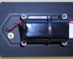
THE LITHIUM-ION BATTERY
The Aristo-Craft, lithium-ion battery will be mounted on the rear of the components platform. Pass a long cable tie through the slot between the components platform and the rear weight. Apply a length of double-sided tape to the side of the battery and fasten it to the platform between the frame posts. Fasten the cable tie around the battery and its connector and charging connector wires as shown. The tie should be snug but not tight. Trim the excess cable tie.

That completes the installation of the battery. It will be connected when the battery switch is installed.
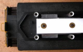
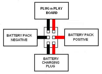
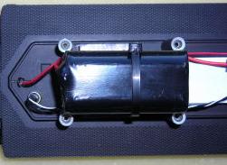
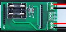
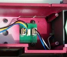
THE PLUG AND PLAY BOARD
Fasten the Plug and Play Board on the components platform between the two holes with the double-sided tape provided or hot-glue. The screw terminals should face the cab.
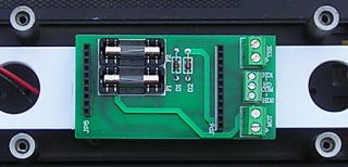
That completes the installation of the Plug and Play Board. It will be wired as the battery switch, motors, and LED lights are installed.
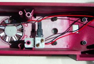
THE BATTERY SWITCH
As the battery will be charged on-board, a Double-Pole, Double Throw, center-off switch will be used to toggle the battery between its charging connector and the receiver mounted on the Plug and Play Board. The switch will be installed in the wall of the fuel tank behind the cab. This will allow it to be accessible, but hidden when running the locomotive.
The DPDT, center-off switch is available from All Electronics under catalog number MTS-12.
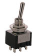
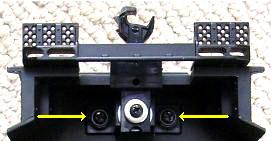
The wall behind the cab is labeled USA Trains on the bottom of the fuel tank. Place a mark 1/2 inch over from the left-hand side of the tank and 1/2 inch down from the top. Drill a hole for the switch using a 15/64 inch bit. Set the fuel tank aside for now.
As it is easier to solder and shrink wrap the wires to the terminals of the switch before it is installed; place the switch in a small bench vise with the terminals facing up.
The male half of the All Electronics, 2-pin connector set shown on the right will be used to connect the lithium-ion battery to the center terminals of the switch.
CAUTION: The wires on the connector sets sold by All Electronics may not be positioned the same as the wires on the connectors of lithium-ion batteries and chargers. If not, click on the following link to see how to switch the positions of the AE Connector Set Wiring so that proper polarity is maintained.
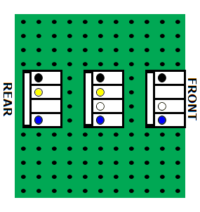
Do not shorten the wires as they must be long enough to easily reach from the battery connector to the switch before the fuel tank is installed. Solder and shrink wrap the wires of the connector to the center terminals of the switch as shown in the following diagram.
Place the vise and switch next to the frame in the fuel tank area. Push the battery connector soldered to the center terminals of the switch through the hole in the center of the frame and the hole in the components platform closest to the battery.
CAUTION: Check that the DPDT switch is in the center-off position. Ensure the colour coding of the wires on the lithium-ion battery connector and the connector soldered to the center terminals of the DPDT switch match. Plug the two connectors together.
Draw the vise back until the wires are fully extended. The position of the vise will ensure the remaining wires will be long enough to allow the switch to be installed before the fuel tank is fastened to the frame.
Solder and shrink wrap a 12 inch long, red wire to the bottom terminal on the right side of the switch as shown in the diagram below. Solder and shrink wrap a 12 inch long, black wire to bottom terminal on the left.
Push these wires through the hole in the center of the frame and the hole in the components platform nearest the pilot on which the charging connector has been mounted. Trim these wires or the wires from the battery charging connector to a suitable length. Solder and shrink wrap the red wires together. Solder and shrink wrap the black wires together.
Solder and shrink wrap a 12 inch long, red wire to the top terminal on the right side of the switch as shown in the diagram above. Solder and shrink wrap a 12 inch long, black wire to top terminal on the left.
Push the wires through the hole in the center of the frame and the hole in the components platform next to screw terminals on the Plug and Board. Trim these wires to a suitable length, strip a bit of insulation off the ends, and tin them. Fasten the black wire under the TRK screw terminal marked with a small triangle, and the red wire under the other.
That completes the wiring of the battery switch. It will be installed when the locomotive is re-assembled.
THE RECEIVER LINKING BUTTON
Part of the process required to link the Revolution receiver to its transmitter involves pushing a linking button. The button will be installed under the frame at the back of the locomotive so it is hidden from view but accessible when needed.
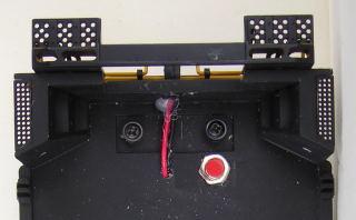
Using one of the washers in the Ziploc bag as a guide, place a mark on the frame under the long hood. Drill a hole in the frame on the mark with a 9/32 inch bit.
Fasten the linking button in the hole without the lock washer. Place both washers in the Ziploc bag.
Lift the cable tie away from the side of the battery and push the linking button connector behind it as shown. Push the battery away from the posts and push the linking button wires down beside the components platform.
That completes the installation of the linking button. It will be connected to the receiver when it is installed.
THE MOTOR BLOCKS
Remove the six screws and the bottom cover from each motor block. Place the screws in a small container so they do not get lost.
Remove the small screws outlined in red from the motor blocks and place them in the small container. Lift the chrome brackets, and remove the track power sliders and wire wipers sprung between the axles. Wipe the grease off them, and place them in the Ziploc bag. Fasten the chrome brackets back in place with the small screws.
Lift the axle sets out. If you can gently turn a wheel while holding the other, the axle sleeve on the drive gear is split. They can be fixed using the method in the DRIVE GEAR AXLE SLEEVES repair tip, or replaced with complete axle assemblies. If you wish to get rid of rubber traction tires, order axle assemblies without them from USA Trains.
Place the axle assemblies back in the motor blocks. Ensure their bushings are seated flat in the slots in the sides of the motors blocks. Pop the covers back on and fasten them with their screws. Do not fully tighten any of the screws until all the screws have been inserted and turned down some. If you fully tighten the screws as you go, the last few may be hard to insert and may strip the threads in the plastic motor block.
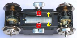
The small and sometimes unreliable slip-on connectors that plug into the front of the motor block will be replaced with wires soldered directly to the motor terminals. Remove the six screws and the top cover from each motor block. Place the screws in a small container so they do not get lost. Remove the small, lash adjusting assemblies from the ends of each motor block and place them in the small container.
Lift the motors out of the blocks. There are four brass rods in each motor block. The two on the outside provide power to the motor terminals and are secured with small screws and plastic washers. Remove the screws and washers and place them in the small container. Remove the outside rods and place them in the Ziploc bag.
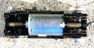
When the motors are wired, it would less confusing if the colour coding of the motor wires matched when fastened under the MOT screw terminal. In order to accomplish this, one motor block has to be wired differently from the other. With the motor terminals facing each other, solder a foot of red wire to each of the top terminals and a foot of black wire to each of the bottom terminals.
If required, lubricate the pinion gears and worm gears with plastic compatible grease. Ensure the worm gears on the motor shafts and the pinion gears on the axles are properly meshed. The wheels should not turn.
Lightly push the red and black wires into the outside channels left by the brass rods that were removed. Secure the wires and inside brass rods using the small screws and plastic washers placed in the small container. Place the lash adjuster assemblies back in their slots in the ends of the motor blocks. If necessary, use a little grease to hold them in place. Set the top covers back on. If the covers are not fitting tightly, check to ensure the lash adjuster assemblies are seated properly. Fasten the covers back on with their screws.
Lay the locomotive on its side on the engine cradle. Remove two of the side frames and install the motor blocks. Fasten the side frames and spring stirrups back on.
Pass the motor wires through their holes in the frame and the hole in the components platform nearest the screw terminals on the Plug and Play Board. Pull the wires taught and trim them 4 inches above the components platform. This extra wire will allow the motor blocks to be turned almost 90 degrees to access the screws that hold the shell to the frame.
Strip a bit of insulation off the ends of the wires and tin them. Fasten the black wires under the MOT screw terminal marked with a small triangle, and the red wires under the other MOT screw terminal. Tug on each wire to ensure they are all fastened securely.
That completes the re-wiring, lubrication, and installation of the motor blocks. Wash any black grease off your hands before proceeding, as it will never come out your clothes.
CHARGING THE BATTERY
Toggling the battery switch up connects the battery to its charging connector.
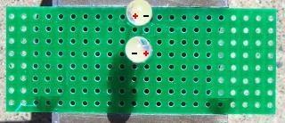
If the battery has not been charged, connect an Aristo-Craft, lithium-ion battery charger to the charging connector on the pilot and toggle the switch up. The green LED on the charger should light up. Plug the charger into an outlet. After about four hours, the battery should be fully charged. Return the switch to its center-off position and remove the charger.
To test the battery, connect the male half of a 2-pin connector set to the charging connector on the rear pilot. Attach a voltage meter to the free end of the wires and toggle the battery switch up. A fully charged Aristo-Craft lithium-ion battery will read up to maximum of 25.2 volts, but anything over 24 volts is suitable. Return the switch to its center off position.
THE RECEIVER
Install the Revolution receiver in the Plug and Play Board ensuring all the pins line up properly. Plug the linking button connector into header on the back of the receiver. Raise the antenna!
The Installation and Operation Manual for the Revolution Train Engineer is on the CD that comes with the set. The Revised Manual and other information is also available on the Aristo-Craft web site as an Adobe pdf file. To read or download the revised manual, click on the link.
Although the headlights are not available for use in this testing procedure, a small red LED on the receiver will flash during the linking process. Toggle the battery switch down, and program the receiver in accordance with the instructions provided in the Installation and Operation Manual.
Place the frame on a test stand or rollers so the wheels can turn freely. Test the motors to ensure they respond properly to the throttle. After testing return the battery switch to its center off position.
That completes the installation, programming, and testing of the Revolution receiver. All that remains to do is add the LED lights to the shell and re-assemble the locomotive.
REMOVING THE FACTORY INSTALLED LIGHTS
Unplug the connector, indicated with the yellow arrow, for the lights in the cab.
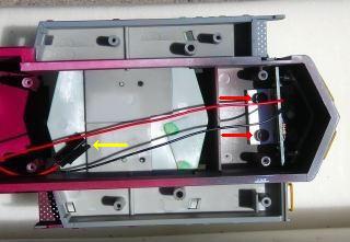
Remove the two screws, indicated with red arrows, holding the printed circuit board for the lights in the short hood. Remove the circuit board and fasten the screws back in the shell.
Remove the two screws, indicated with yellow arrows, holding the printed circuit board for the lights in the long hood. Lift the printed circuit board back but not too far as the headlight bulbs are wired to it. The long hood number boards are lightly glued to the shell and should pop out with a gentle push. Set them aside for now. The headlight lenses and bulbs are also lightly glued to the shell and should pop out with a gentle push. Remove the circuit board and fasten the screws back in the shell.
There is a grey plastic part lightly glued to a post in the middle of the long hood. Gently wiggle the part up off the post.
Place the light boards and their wiring in the Ziploc bag.
If you do not intend to use smoke, remove the four screws holding the smoke unit and the small printed circuit board to the top of the shell. Place the parts in the Ziploc bag, and fasten the screws back in the shell.
Open each of the cab doors and remove the screws holding the springs to them. Fasten the screws back in the cab doors so they do not get lost or mixed up with others.
There are four tabs on the bottom of cab holding it to the battery boxes. Gently push each of the tabs in slightly with a flat screwdriver until they release and let that corner of the cab lift slightly. When all four tabs have been released, the cab should lift straight up and off.
Remove the four screws from inside the top of the cab.
Flip the cab over and lift the center of the roof straight up off its four posts. It is a snug fit. Remove the two screws holding the Printed Circuit Board to the cab.
The headlight lenses are part of a black plastic holder for the bulbs hot glued above the number boards. Heat the glue with the tip of a hot glue gun and remove the holder bulbs and all. An inexpensive IC extractor available from All Electronics under catalog number EX-1 will make removing the plastic holder easier.
If you do not have one, try gently tapping the plastic headlight lenses out using a small plastic tube or wooden dowel. Place the PCB and headlight bulbs in the Ziploc bag with the rest of the electronics. Fasten the two screws back in the cab so they do not get lost or mixed up with others.
Place the roof back on its posts and fasten it with its four screws. Any windows that fell out while the cab was being handled can now be fastened back in. How did I know?
That completes the removal of all the factory lights and their wiring.
LED LIGHTS FOR THE CAB
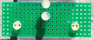
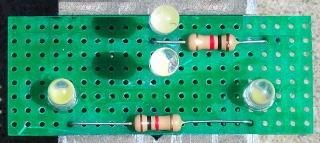
The LED headlights and number board lights for the cab will be soldered to a perf board which will be mounted in the roof above the windows.
The flangeless LEDs, straight trace perf board, and 1/2 watt 1K resistors are all available from All Electronics under catalog numbers LED-115, ECS-4, and 293-1K respectively.
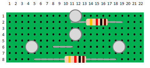
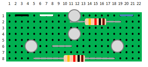
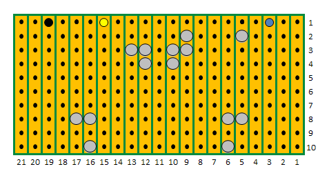
Using an awl and X-Acto knife, score and snap a piece of the perf board 22 traces across and 8 rows deep. The perf board must be scored on both sides before being snapped. Sand the edges smooth.
The bottom of the cab headlight LEDs must be installed 9/16 of an inch above the component (green) side of the perf board in order for them to fit properly in the cab. Strip 2 inches of insulation off a 22 gauge red wire, and 2 inches of insulation off a 22 gauge black wire. Cut 2 pieces exactly 9/16 of an inch long from each piece of insulation. Slip the red pieces over the anodes (longer leads) of 2 flangeless bright white LEDs. Slip the black pieces over the cathodes (shorter leads).
In the top row of the component side of the perf board, insert the red lead of an LED in the 11th trace from the left edge and the black lead in the 12th trace beside it. Use a toothpick to apply a bit of gap filling CA (super glue) to the bottom of the insulation on each lead. Ensuring the leads remain perpendicular, press the LED against the board until the glue on the bottom of the insulation dries. The glue will dry quickly if the perf board is held over an open bottle of CA accelerator (kicker).
In the 4th row from the top of the board, insert the black lead of an LED in the 11th trace from the left edge and the red lead in the 12th trace beside it. Use a toothpick to apply a bit of gap filling CA to the bottom of the insulation on each lead. Ensuring the leads remain perpendicular, press the LED against the board until the glue on the bottom of the insulation dries.
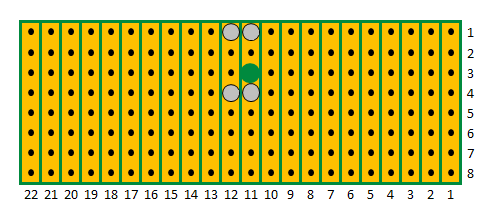
Turn the perf board over; flux and solder the leads of the LEDs in place. Count 3 rows down from the top, and with a 1/8 inch bit in a pin vise, open the 11th trace from the right edge of the board as indicated with the big green dot.
Test fit the circuit board in the cab. The circuit board should touch the sides of the number boards. The LEDs should bulge beyond the top of their housing, but not beyond the visors on the bottom.
On the component side of the board count down 6 rows from the top and insert the shorter negative lead of an LED in the 4th trace from the left edge, and longer positive lead in the 5th trace beside it.
In the same row, insert the shorter negative lead of an LED in the 18th trace from the left edge, and longer positive lead in the 19th trace beside it. Glue the bottom of both LEDs to the perf board with super glue so they will remain in place and flush to board when you flip it over to solder. Flip the board over; flux and solder the leads.
Turn the board over to the green component side, and count down 2 rows from the top of the board. Bend the leads of a 1K resistor so they will fit in the 11th and 19th traces from the left edge. Hold the resistor to the board with self-closing tweezers so it will remain in place and flush to board when you flip the board over to solder it. Flip the board over; flux and solder the leads.
Turn the board over to the green component side. Bend the leads of a 1K resistor so they will fit in the 5th and 18th traces from the left edge, in the bottom row. Flip the board over, and flux and solder the leads.
On the green component side count three rows up from the bottom. Using a piece of solid wire, bend a jumper that will fit in the 8th and 11th traces from the left edge.
Flip the board over, and flux and solder the leads. Using a pair of side cutters, trim all the component leads on the board.
A flat, six wire, telephone cord has all the colours of wire required to wire both LED lighting circuit boards. If you model in a smaller scale, you may have some left over from your DCC LAN. The wires will fit through the holes in the perf board, are large enough to carry the required current for the LED circuit boards, and are flexible enough to be grouped together when connecting the shell to the Plug and Play Board.
UPDATE: The telephone cord wires have proven to be too fragile and broke at solder joints and screw terminal connections. It is recommended that 26 gauge wire be used instead.
Strip a length of insulation off the telephone cord and cut 12 inch black, white and blue wires from it. On the solder side of the perf board, push a couple of inches of the black wire through the 2nd trace from the right edge, the white through the 6th trace, and the blue wire through the 21st trace.
Flip the board over to the component side and strip a bit of insulation off the ends of all three wires. Place the end of the black wire in the 4th trace from the left edge, the white wire in the 8th trace, and the blue wire in the 19th trace. Draw the wires back until there is a small loop above the board in each. This will keep the wires in place when you turn the board over to solder.
Flip the board over; flux and solder the wires to the perf board. Clean both sides of the board with flux remover or rubbing alcohol. Running an awl between the traces will remove any flux build up and make it obvious if there is solder overlapping the traces.
That completes the assembly of the cab LED lights.
INSTALLING THE CAB LEDS
Slip the headlights into the roof of the cab and slide the circuit board forward until it touches the number boards on both sides. Fasten the edges of the circuit board to the top of the roof with hot glue.
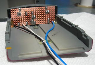
Pinch the wires together towards the back of the roof and apply a run of hot glue to keep them in place. If the horns are loose, apply a dab of hot glue on their peg behind the circuit board. If you do not intend to open the cab doors, fasten them shut with a spot of hot glue. Remove the four small screws from the cab. Pass the wiring through the slot in the back of cab. Set the roof on its four pegs and fasten it with the screws.
The wiring for the lights fits through a small slot in the back of the cab. The cab slides into grooves in the hood. It should slide on smoothly until the four tabs on the bottom of cab click onto the battery boxes. There should be no space between the bottom of the cab and the battery boxes. If there is, check the placement of the wires.
If you have not fastened the cab doors closed with hot glue, open them and remove the tiny screw from each. Fasten the small spring back on each door.
That completes the assembly and installation of the cab LEDs. They will be connected to the Plug and Play board after the rear LEDs are assembled and installed.
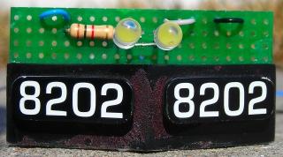
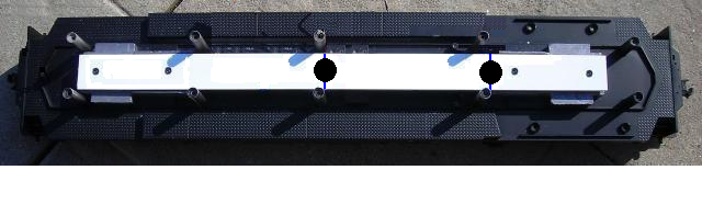
LED LIGHTS FOR THE LONG HOOD
The LED headlights, LED number board lights, and number boards will be fastened to a perf board which will be mounted in the rear of the long hood.
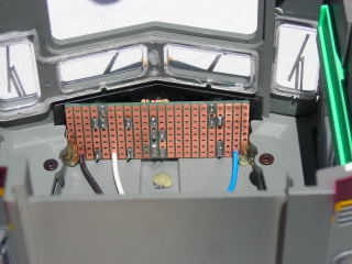
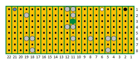
Using an awl and X-Acto knife, score and snap a piece of the perf board 21 traces across and 10 rows deep. Sand the edges smooth.
The bottom of the rear LED headlights must be installed 5/8 of an inch above the component (green) side of the perf board in order for them to fit properly. Strip 2 inches of insulation off a 22 gauge red wire, and 2 inches of insulation off a 22 gauge black wire. Cut 2 pieces exactly 5/8 of an inch long from each piece of insulation. Slip the red pieces over the anodes (longer leads) of 2 flangeless bright white LEDs. Slip the black pieces over the cathodes (shorter leads).
On the component side of the perf board, count down 3 rows and insert the red lead of an LED in the 9th trace from the left side, and the black lead in the 10th trace beside it. In the same row, insert the red lead of an LED in the 12th trace from the left side, and the black lead in the 13th trace beside it. Use a toothpick to apply a bit of gap filling CA (super glue) to the bottom of the insulation on each lead. Ensuring the leads remain perpendicular, press the LEDs against the board until the glue on the bottom of the insulation dries.
Count 4 rows down from the top. Using a piece of solid wire, bend a jumper that will fit in the 10th and 12th traces from the left side. Flip the board over; flux and solder all the leads in place.
On the component side of the perf board count down 8 rows from the top, and insert the longer positive lead of an LED in the 5th trace from the left side, and the shorter negative lead in the 6th trace beside it. In the same row, insert the longer positive lead of an LED in the 16th trace from the left side, and the shorter negative lead in the 17th trace beside it. Fasten the bottoms of the LEDs flush to the perf board with CA.
Flip the board over; flux and solder the leads.
On the component side of the perf board count down 2 rows from the top, and bend the leads of a 1K resistor so they will fit in the 5th and 9th traces from the left edge. Flip the board over; flux and solder the leads.
On the component side of the perf board, bend the leads of a 1K resistor so they will fit in the 6th and 16th traces from the left edge, in the bottom row. Flip the board over; flux and solder the leads. Using a pair of side cutters, trim all the leads on the solder side of the perf board.
Strip a length of insulation off the 6-wire telephone cord, and cut 18 inch long blue, yellow and black wires from it. In the top row of the solder side of the board, push the blue telephone wire through the 3rd trace, the yellow wire through the 15th trace, and the black wire through the 19th trace.
Flip the board over to the component side and strip a bit of insulation off the ends of all three wires. Place the end of the blue wire in the 5th trace from the left edge, the yellow wire in the 13th trace, and the black wire in the 17th trace. Draw the wires back until there is a small loop above the board in each. This will keep the wires in place when you turn the board over.
Flip the board over; flux and solder the wires to the board. Clean both sides of the board with flux remover or rubbing alcohol.
Cut two pieces of 1/8 inch thick styrene strip 9/16 of an inch long. Glue them to the bottom corners of the component side of the perf board as shown. Using the top of the shims as a guide, take the gloss off the perf board between rows 4 and 5 with a flat file. This will allow the CA used to fasten the number boards to the perf boards to hold. Wipe the board clean.
Lightly sand the back ridge on the back of the number boards. Wipe it clean. Glue the ridge of the number boards to the line above the top of the shims, ensuring the sides of the number boards are flush with the sides of the shims and perf board.
When that glue has dried use a toothpick to run a line of glue along the sides of the number boards and shims. That completes the assembly of the LED circuit board for the long hood.
INSTALLING THE REAR LEDS
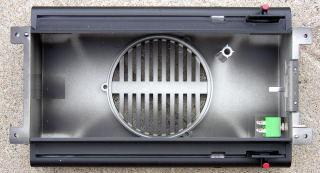
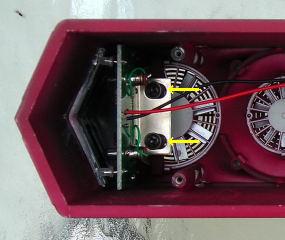
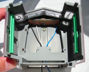
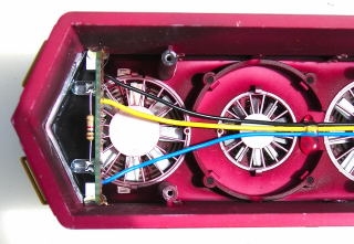
Slip the headlights and number boards into the rear of the long hood. If they will not clear the bar at the top of the shell, remove the two screws from it. If they still will not clear, pop the fan above them out of the hood. Set the shell on a flat work surface. Using a piece of hardwood dowel and a small hammer, gently tap through the fan hole on each end of the bar until the glue releases it. It may come out in one piece, but if not if not there is always super glue. Place the screws back in the bar, and place the bar in the Ziploc bag with the electronics.
Fasten the bottom edges of the circuit board to the sides of the shell with hot glue. Pinch the wires together behind the second fan on the hood and apply a run of hot glue to keep them in place.
TESTING THE LED LIGHTS
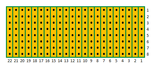
Strip a bit of insulation off of all six wires from the LED circuit boards. Fasten the ends of the two blue wires under the screw terminal on the PnP Board marked HD COM. Fasten the yellow wire under the screw terminal marked HD1, and the white wire under the screw terminal marked HD2. Fasten the two black wires under the TRK screw terminal marked with a small triangle along with the black wire from the battery switch. Give each of the wires a tug to ensure they are securely fastened. It may be necessary to solder the three black wires together.
When the battery switch is toggled down to power the receiver, the number board LEDs will come on full bright. With the first push of the transmitter/throttle (1% power) the headlight LEDs will come on full bright. If the direction of the motors and the headlights are not the same, the can be changed using the Assign Functions menu on the transmitter, or reversing the yellow and white wires. When testing is complete, turn the battery switch off.
OPTIONAL CONNECTOR FOR THE LED LIGHTS
A small interface board with plug-in connectors could be mounted in the long hood allowing the LED circuit boards to be plugged into it. A third connector would connect the interface board to the PnP board with just four wires: one to the each of the three lighting screws terminals, and one to the TRK screw terminal marked with a small triangle along with the black wire from the battery switch. This would allow the shell to be installed or removed using the third connector with all the wires for the LED boards and PnP Board remaining in place.
Score, snap, and sand a piece of perf board 11 rows across by 13 traces down.
On the component side of the perf board, use CA to fasten 4-pin headers in rows 2, 6, and 10; in traces 3 through 6 as shown.
The 4-pin headers and 4-wire connectors are available from Active Electronics under catalog numbers 37-6204-5 and 37-604-4.
Flip the board over. Flux and solder the pins to the board. Clean the board with flux remover or rubbing alcohol. Mount the board under the screws in place of the smoke unit circuit board as shown. If the smoke unit has been maintained, mount the interface board on the wall of the shell with hot glue at the corners.
Strip a length of insulation off the 6-wire telephone cord, and cut 12 inch blue, yellow, white, and black wires from it. Strip a small bit of insulation off one end of each wire. Crimp the terminals that came with the connectors to the end of the wires.
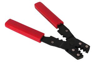
Although it possible to crimp the small metal terminals to the wires with needle nose pliers, it is a tedious process. The proper tool is a D-sub crimper. An inexpensive one is available from All Electronics under catalog number CT-1. These are an invaluable tool when working on the wiring of large scale locomotives.
Insert the metal terminals of the wires in a connector using the following diagram as a guide. Plug the connector into the center of the interface board.
Cut the wires from the cab LED circuit board to a length that will easily reach the interface board. Strip a small bit of insulation off the end of each wire and crimp terminals to them. Insert the terminals into a connector using the diagram above as a guide. As there is no yellow wire, there will be a space between the white and blue wires. Plug the connector into the front of the interface board as shown.
Cut the wires from the long hood LED circuit board to a length that will easily reach the interface board. Strip a small bit of insulation off the end of each wire and crimp terminals to them. Insert the terminals into a connector using the diagram above as a guide. As there is no white wire, there will be a space between the yellow and black wires. Plug the connector into the back of the interface board as shown.
Strip a little bit of insulation off the free ends of the four wires in the center connector. Flux and tin them. Slip a couple of bands of shrink wrap over all the wires at 4 inch intervals and warm the bands until they are snug.
Fasten the end of the black wire under the TRK screw terminal on the PnP Board marked with a small triangle along with the black wire from the battery switch. Fasten the end of the white wire under the screw terminal marked HD2, the yellow wire under the screw terminal marked HD1, and the blue wire under the screw terminal marked HD COM. Give each of the wires a tug to ensure they are securely fastened. It may be necessary to solder the two black wires together.
Toggle the battery switch down to power the receiver, and the number board LEDs will come on full bright. With the first push of the transmitter/throttle (1% power) the headlight LEDs will come on full bright. If the lights and the motors are not in operating in the same direction, reverse the direction of the lights on the throttle using ASSIGN FUNCTIONS menu, or reverse the positions of the white and yellow wires. When testing is complete, turn the battery switch off.
RE-ASSEMBLING THE LOCOMOTIVE
If the smoke units have not been removed, attached an Aristo-Craft, Smoke Unit Control Board and fasten the power wires under the MOT terminals of the Plug and Play Board.
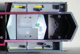
Set the shell on the engine cradle beside the frame. Remove the four shorter screws from the battery boxes and the ten longer screws from the shell and place them in a small container.
Slide the shell over the frame posts ensuring that none of the wires get caught between the shell and the frame. The whole shell should sit flush against the frame without being forced. Carefully place the locomotive upside-down on an engine cradle or other soft surface, taking care not to damage the horns.
As there has been 4 inches of slack included in the motor wires, the motor blocks can be turned almost 90 degrees to install the screws through the frame into the shell and battery boxes. Ensure the motor wirers do not get pinched between the top of the motor blocks and the sides of the frame.
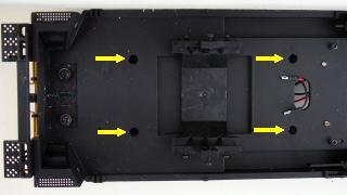
Insert the four shorter screws outlined with yellow that hold the battery boxes to the frame and fasten them a few turns.
Insert the ten longer screws indicated with yellow arrows that hold the shell to the frame and fasten them a few turns.
Four in the front motor block area.
Two in the fuel tank area.
Four in the rear motor block area.
Tighten all 14 of the screws down.
Remove the screws indicated with the yellow arrows from the frame, and fasten the brackets and couplers to the frame.
Install the battery switch in the front wall of the fuel tank so it toggles up and down. If you intend to label the switch, do it before installing the fuel tank. Remove the four screws from the center of the frame and install the fuel tank.
Install the handrails to the sides and ends of the locomotive.
CONGRATULATIONS! You have successfully installed on-board: battery power, radio control, and LED lights in your GP-30. ENJOY!
5 comments
Skip to comment form
TO WHOM IT MAY CONCERN: All Electronics does not list the LED-115, they do list an LP-715 is that the same LED? Thanks for your help. Bernie
Hi Paul, I really appreciate the step by step guide to converting the USA Trains GP30 to remote control and battery operation. I have a question concerning upgrading the lights to LED. What happens to the directional red/green lights on each end of the loco?
Thanks,
Scott
Marker lights are only used if the locomotive is run by itself.
We delete them to save battery power.
The bright LED headlights are a good indication on what direction the locomotive is going to move even in daylight.
Thanks Jack!
I am glad you find these articles helpful.
Your site has some of the best projects I’ve seen anywhere on the web for large scale trains. I appreciate all the effort that went into projects such as converting a USA Trains GP-30 to Revolution wireless operation. I could have done it, but you guys saved me countless hours. Canadians are awesome!
Jack