
This project shows how to add an MU connector to the rear of a Bachmann 0-4-0 steam locomotive so a trailing power and control car can be used to run it. A power and control car is simply a battery car with a receiver added for on-board radio control.

To view articles on how to build a Power and Control Car, just click on the link.
As the locomotive will be run with battery power, it is imperative that the track power wiring be removed to ensure the locomotive cannot pick up track power or feed battery power into the tracks. The result could be electronically catastrophic. Nothing prevents the locomotive from being restored to its original condition for re-sale at a later date however, as any parts removed will be stored intact in a Ziploc bag.
Turn the locomotive over and place it on a foam lined engine cradle or the Styrofoam insert it came in. Remove the two screws (circled in yellow) from the steps under the rear coupler and remove the steps. This will eliminate the need to remove the coupler as I did.
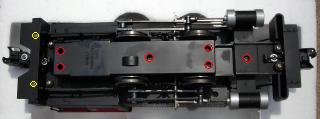
Then remove the six shorter screws (circled in red) from the bottom cover of the motor block and between the front cylinders. Place all the screws in a small container so they do not get lost or mixed up with others. Gently lift the motor block bottom cover off.
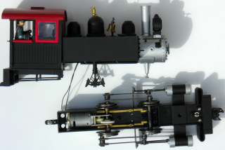
After removing the boiler stays between the smoke box and the front pilot, the drive mechanism can be separated from the boiler and cab.
The track power pick-ups to be removed are the brass strips running under both axles and beside the motor.
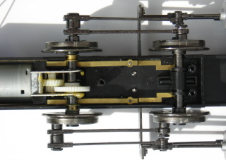
Start by swinging the front axle back over the motor.
Remove the two tiny chrome screws (circled in red) on each side of the motor block holding the spring loaded axle rubbing devices. Be careful not to lose any of the parts, as these devices will be put back to steady the axle.
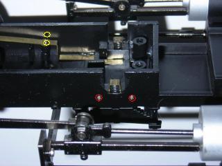
Remove the tiny, chrome screw (circled in yellow) from the center of each brass strip. Remove the two, front pieces of brass strip. Place them in a Ziploc bag labeled Bachmann 0-4-0 along with the road name and number.
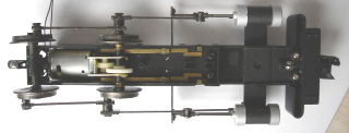
Replace the axle rubbing devices, and swing the front axle back into position.
NOTE: If you encounter as much difficulty as I did replacing these devices, dip the end of the springs in a puddle of CA (superglue) and glue them to the motor block.
The rear portion of the brass strips are glued to the sides of the motor block. Using a razor knife or similar tool, pry the strips off the walls of the motor block.
There are two wires soldered to the end of each of the rear brass strips: one from the motor and one from the headlight. Unsolder these wires.
There is a wire soldered to each of the motor tabs. Unsolder these wires. Place the small motor wires and the rear brass strips in the bag with the other parts. Place the bag in one of the small crevices in the Styrofoam packing and stick a piece of tape over it.
The male half of a 2-wire connector set is required for this project. The connector set is available from All Electronics under part number CON-240. OVGRS member can purchase it by contacting Paul Norton.
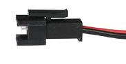
Unplug the female half of the connector set and set it aside. It can be used for a power and control car connector or lithium-ion battery pack charging connector in other projects.
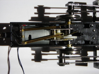
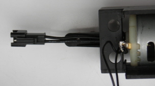
Turn the chassis over and drill a 1/8 inch hole in the back of the motor block just above the coupler mounting bracket.
With the locking tab of the male connector facing up, run the two wires of it through the hole until the connector is the same length as the coupler. As I did not have the coupler in place, the leads on the connector shown in the picture below are a little short.
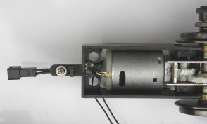
Trim the wires so they will easily reach the motor terminals. Solder one of the connector wires and one of the headlight wires to each of the motor terminals.
Roll the chassis over and place a glob of hot glue on the connector wires inside the motor block for strain relief.
Now is a good time to apply some grease to the gears and oil the motor bearings.
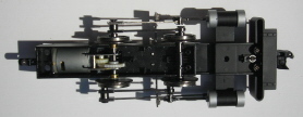
Place the boiler and cab on top of the chassis and fix the motor block and its cover in place with five of the shorter screws (circled in red). Re-install the screw (circled in red) between the cylinders, and the two longer ones (circled in yellow) holding the steps on the back pilot. Turn the locomotive over and install the two boiler stays between the smoke box and the front pilot.
If the back of the engine block does not want to fit, ensure the top motor tab is bent straight up, not flat as shown in previous photos, so it will clear.
The upper portion of the coupler pin may have to be filed or sanded down so it will not interfere with the swing of the connector and coupler.
CONGRATULATIONS! This new connector will allow you to run your Bachmann 0-4-0 with a power and control car and enjoy all the benefits of battery power and radio control.