
The Aristo-Craft, 75 MHz, on-board receiver was released in 2002. At that time there was a promise of 100 feet of radio range, which was more than double that of its 27 MHz predecessor. When used in a trailing power car or steam tender the promised range was possible if the transmitter was equipped with a telescoping antenna.
When the receiver was mounted inside a powered locomotive however, radio frequency interference (RFI) generated by the motor(s) interfered with the transmitter’s reception. Even at slow speeds and close radio range, the locomotive was difficult to slow down and is some cases could only be stopped with the Emergency Stop key on the transmitter.
Over the years I experimented with RFI suppression components, capacitors across the motor terminals and chokes in the motor leads, to try and resolve the problem. Unfortunately I had mixed results and finally conceded this was not a workable solution. After the introduction of the new 2.4 GHz Revolution receiver in the spring of 2009, I sold all my 75 MHz equipment. The new 2.4 GHz receiver has excellent radio range, a host of new features, and a lower price.
75 MHZ RECEIVER INSTALLATION
The connector with its seven coloured wires must be removed (snapped off) from the main circuit board before the 75 MHz receiver can be used.
If the steam locomotive has a Plug and Play port in the tender, remove the dummy plug from it and install the front 12 pins of the receiver in its place.
- If the connector is to be used to install the receiver in the tender of a non Plug and Play locomotive, the seven wires on the connector must be connected to the locomotive as follows:
- Red – Track Power Left Side or Battery Switch Positive Terminal
- Orange – Motors Terminals Left Side
- White – Front Headlights (negative)
- Blue – Lights Common (positive)
- Yellow – Rear Headlights (negative)
- Grey – Motors Terminals Right Side
- Black – Track Power Right Side or Battery Switch Negative Terminal
If the motor(s) and light(s) are not working the same direction, change the motor wires over.
- If the adapter is used in trailing power car:
- The Red wire is connected to the Battery Switch Positive Terminal, and the Black Wire to the Battery Switch Negative Terminal.
- Orange and Grey wires are attached to the MU plug
RECEIVER ANTENNA
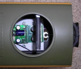
To maximize radio range, the receiver antenna must be mounted as high as possible in the locomotive or trailing car and must not cross over itself.
Although it may not provide any greater range than the wire antenna, the Black Kat from E Cubed R/C shown below is easier to mount because of its small size.
TRANSMITTER ANTENNA
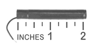
Early 75 MHz transmitters were sold with a short, rubber covered antenna. As radio range and response with these antennas can be very poor, it should be replaced it with a telescoping antenna from Aristo-Craft.
RADIO RANGE PROBLEMS
- If you do not obtain the expected radio range, check the following:
- Are the batteries in your transmitter fairly new? Aristo-Craft recommends using Coppertops or similar batteries. Rechargeable batteries do not have the same voltage and decay when left sitting.
- Is your track power or trailing car battery pack(s) fully charged to at least 18 volts? According to rumor, the 75 MHz receiver responds better at higher voltages.
- Are you holding the transmitter antenna straight up?
- Are you standing under the metal frame of a gazebo or other structure?