
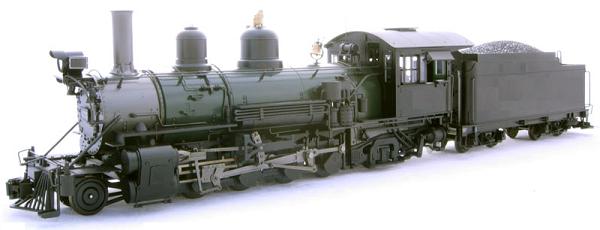
This article details the conversion of a Bachmann K-27 steam locomotive from track power to on-board, battery power and radio control.
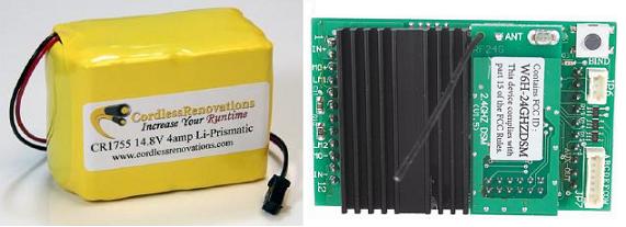
The main components used are a Cordless Renovations Lithium-Prismatic battery (CR1755), and an Aristo-Craft Revolution receiver (CRE57002).
As Bachmann has placed all the required electronics in the tender of the K-27, the locomotive itself will not be altered in any way during this power conversion. Furthermore, nothing in this conversion prevents the tender from being returned to its original condition for re-sale at a later date.
Please read this article carefully, highlighting the components that are needed. Sources of supply are suggested for items not sold by your hobby suppliers. OVGRS members can purchase the required electronic components by contacting Paul Norton.
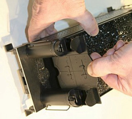
OPENING THE TENDER
To access the interior of the tender, pull up the coal doors panel, and remove the coal load.
Use a Phillips, number 2, screwdriver to remove the 3 screws holding the tender body to the frame.
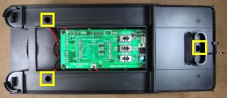
Put the coal doors panel and coal load back on the tender body, and set it aside for so it does not get damaged. Fasten the three screws back in the frame so they do not get lost or mixed up with others.
TRACK POWER PICK-UPS
It is imperative that the track power pick-ups be disconnected to ensure they cannot pick up track power or feed battery power into the tracks. The result could be electronically catastrophic.
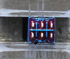
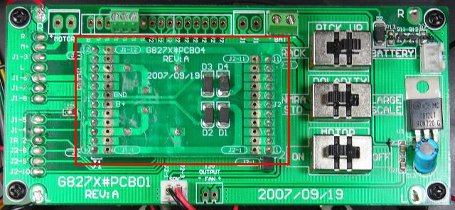
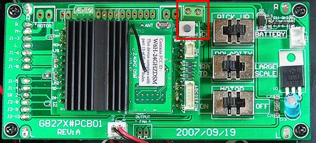
On the K-27 Plug and Play (PnP) circuit board is a track power/battery power switch labeled PICK UP. In the battery power position, all track power connections in the tender and locomotive are turned off. Slide the switch to the BATTERY position.
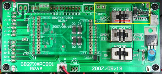
To ensure the pick-up switch cannot be inadvertently re-positioned, place as small dab of hot glue behind the switch lever.
CONTROL PANEL
A control panel is required to hold the battery switch, its charging connector, and a programming jack for a sound board. The installation of a Phoenix Sound P8 in a Bachmann K-27 is detailed in another article on this web site. To view it, just click on the link.
Cut a piece of 1/8 inch thick styrene, 2 3/4 inches long, by 1 3/4 inches wide. Draw a line across the center of the panel lengthways. Place a mark on the line every 11/16ths of an inch.
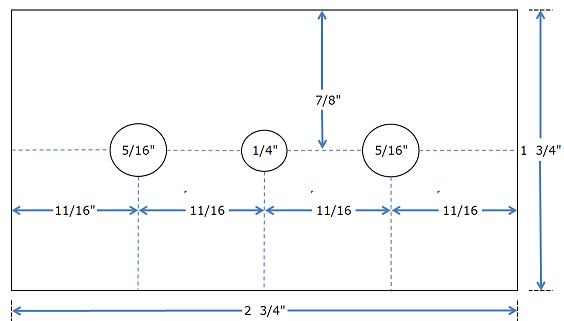
Drill a hole on the center mark with a 1/4 inch bit for the battery switch.
Drill a hole on the other two marks with a 5/16 inch bit for the battery charging connector and the optional Phoenix Sound programming jack.
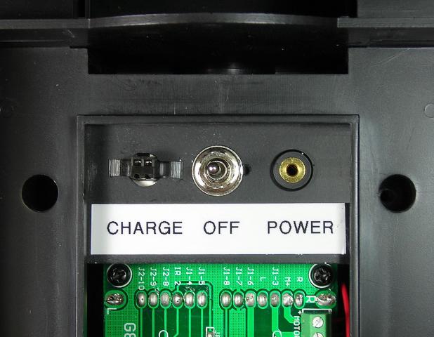
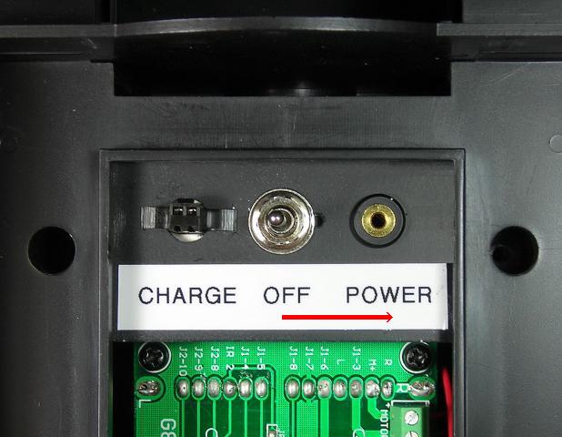
Paint the top of the panel. Once the paint has cured, fasten the bottom of the panel in place with hot glue, and label the top. The charging connector, battery switch, and optional sound board programming jack will be added next.
BATTERY SWITCH
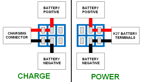
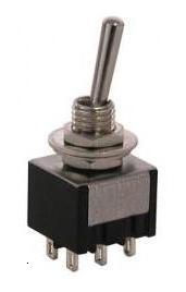
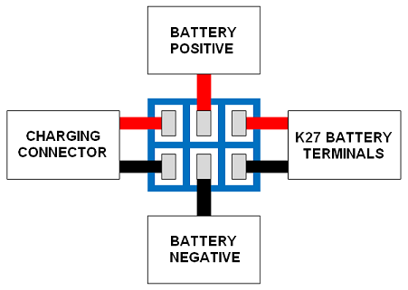
As the battery will be charged on-board; a double pole, double-throw (DPDT) center-off switch is required to toggle battery between its charging connector and the battery power screw terminals on the K-27 Plug and Play (PnP) circuit board.
The DPDT center-off switch is available from All Electronics under catalog number MTS-12.
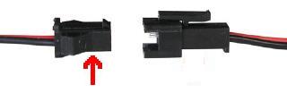
The male half of an All Electronics 2-wire connector set will be used to hook up the battery to the center terminals of the battery switch. It has the same connector as the Cordless Renovations Smart Charger.
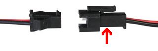
Two-wire connector sets are available from All Electronics under catalog number CON-240.
CAUTION: The wires on the connector sets sold by All Electronics may not be positioned the same as the wires on the connectors of lithium-ion batteries and chargers. If not, click on the following link to see how to switch the positions of the AE Connector Set Wiring so that proper polarity is maintained.
As it easier to wire the switch before installing it, place the switch in a small workbench vise with the terminals facing up.
Cut the wires of the male connector to 4 inches in length, and strip a bit of insulation off the ends. Solder and shrink wrap the wires to the center terminals of the DPDT switch as shown in the following diagram.
The female half of the two-wire connector set will be used as the battery charging connector. It has the same connector as the Cordless Renovations lithium-prismatic battery.
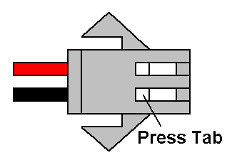
Remove each of the wires from the connector shell by pressing on the small tab on the back of its metal terminal, and gently pushing on the front of the terminal with a small screwdriver. After the terminal has moved, it can be withdrawn by pulling on its wire. Place the connector shell in a small container for now.
Cut the wires of the charging connector to 4 inches in length, and strip a bit of insulation off the ends. Solder and shrink wrap the wires to the terminals on the left side of the switch as shown in the following diagram.
A red and a black wire are required to connect the battery switch to the battery screw terminals on the K-27 PnP circuit board. Cut each wire to 8 inches in length, and strip a bit of insulation off the ends. Solder and shrink wrap the wires to the terminals on the right side of the switch as shown in the preceding diagram.
CAUTION: Check to ensure all the wiring on one side of the battery switch is red, and all the wiring on the other side is black.
Install the battery switch in the center hole of the control panel so it toggles left and right. Looking at it from underside of the panel, the charging connector wires should be on the left terminals of the switch, and the wires for the battery screw terminals on the K-27 PnP circuit board on the right.
Pass the wires for the charging connector through the hole to the right of the switch. Check to see if the small tabs on the metal terminals are raised slightly. If not, use the tip of an X-Acto knife blade to do so.
Push the metal terminal on the red wire into the back of the charging connector at position 1. The number can only be seen with a lighted magnifier. If you do not have a lighted magnifier, just ensure it is in the same position as the red wire on the battery. Push the metal terminal of the black wire into position 2 in the back of the charging connector. Test each wire to see they are locked in place.
Spread the wings of the charging connector 90 degrees. Ensure the locking nub of the connector is facing forward. Wiggle the base of the charging connector through its hole in the top of the control panel.
Slide the prongs of a 1/4 inch spade connector across the base of the connector on the underside of the control panel to hold it in place. Secure the spade bit with a dab of hot glue.
OPTIONAL: If you intend to install a Phoenix Sound board, install the programming jack in the remaining hole in the control panel. To get the nut over the white connector on the end of the wires, push the black wire together with the red and yellow wires. Push the nut over the black wire, and slip the nut down off the other end of the connector.
That completes wiring of the battery switch and the control panel. The battery and battery screw terminals on the K-27 PnP circuit board will be connected to the control panel wiring, after the receiver and battery are installed.
REVOLUTION RECEIVER
Remove the DC plug from the front of the K-27 socket.
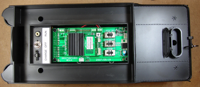
Install the Revolution receiver, ensuring the pins on both ends line up properly in the PnP socket. The linking button on the receiver should be towards the rear of the tender.
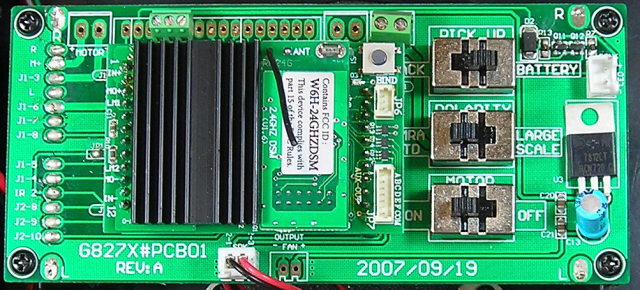
Straighten the antenna
LITHIUM-PRISMATIC BATTERY
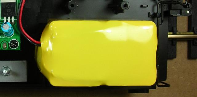
A Cordless Renovations, 14.8 volt, 4000 mah, Lithium-Prismatic battery (CR1755) will be used to power the Revolution receiver, which in turn will power and control the locomotive. To counterbalance the weight of the battery, the weight stacks on the sides of the frame will have to be adjusted.
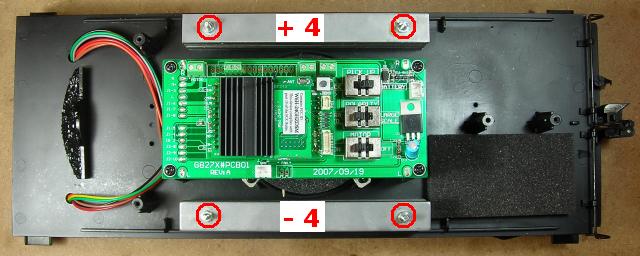
Remove the nut from each of the four bolts holding the weight stacks to the frame. Remove four strips from the weight stack on the side of the frame with the battery, and place them on the other weight stack. Fasten both stacks to the frame with the four nuts.
Use a couple of strips of double-sided tape to fasten the battery in the rear corner of the frame. It should be placed 1/4 inch away from where the rear and side wall of the tender body will sit to avoid contact with the ends of the grab irons. As the mounting posts in the tender body are larger than the posts on the frame, leave a gap between the posts and the pack.
Remove the three screws from the mounting posts and place them in a small container so they do not get lost. Test fit the tender body to the frame.
Check to ensure the colour coding of the wires on the lithium-prismatic battery connector and the connector soldered to the center terminals of the battery switch match. Check to ensure the battery switch is in the center-off position. Plug the two connectors together.
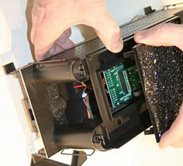
Select a piece of foam not less 3/4 inches thick, but not more than 1 inch thick. Cut a piece 1 3/4 inches wide by 3 inches long, and fasten it to the inside of the tender body above where the battery will sit. A light coat of spray glue on the foam is sufficient. This foam pad should help secure the battery when the tender body is fastened to the frame.
ASSEMBLING THE TENDER
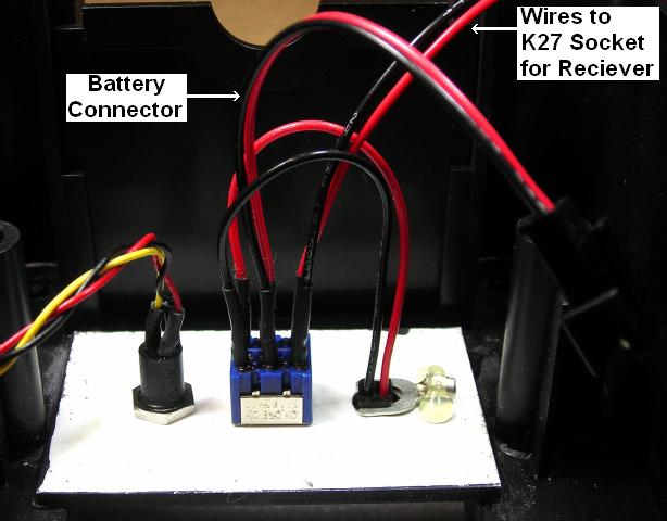
Lay the tender body on its side on a slab of foam beside the frame. Strip a bit of insulation off the free end of the red and black wires on the battery switch and tin them.
On the side of the K-27 PnP circuit board is a set of screw terminals labeled + BATT -. They are right above the linking button on the receiver. Fasten the red wire under the + screw terminal and the black wire under the – terminal.
Place the tender body on top of the frame ensuring the battery switch wires are tucked out of the way. Fasten the tender body to the frame using the three screws in the small container. Slide the coal doors panel into the front of the tender.
OPTIONAL: Drill a very small hole in the front of the coal load just large enough to let the shaft of a black map pin pass through. Cut the point off the end of the pin shaft to blunt it, and pass the shaft through the hole. Bend the bottom 1/4 inch of the pin shaft 90 degrees.
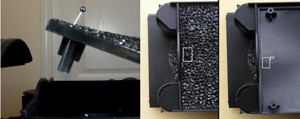
The pin can now be used to lift the front of the coal load to access the charging connector, battery switch, sound board programming jack, and linking button on the receiver without removing the coal doors panel.
PROGRAMMING THE RECEIVER
To power the receiver, toggle the battery switch on the control panel to the right.
The information on how to program the receiver is in the Installation and Operation Manual for the Revolution Train Engineer that is on the CD that comes with the set. The Revised Manual and other information is also available on the Aristo-Craft web site as an Adobe pdf file. To read or download the revised manual, click on the link.
After programming the receiver, place the locomotive and tender on a section of track or test stand, and connect them together. Test the locomotive to ensure it responds to the transmitter and the headlight works properly.
CONGRATULATIONS! You have successfully converted your Bachmann K-27 to on-board, battery power and radio control. ENJOY!