
This is the first of three articles detailing a method to convert a USA Trains F3-A F3-B diesel set from track power to on-board battery power, radio control and sound. The first article will illustrate how to add a Cordless Renovations lithium-ion battery, RCS battery switch with charging jack, Plug and Play Board, 10 amp RailLinx 900 receiver, and Lights Relay Board. The second article will show how to add a Phoenix Sound P8, and the third how to MU an F3-B. All of the required electronic components for these conversions are available from Remote Control Systems of New England.
Please read the articles carefully, highlighting the components that are needed. These articles appear long because they are detailed and includes a lot of pictures. But if you take your time and follow them step-by-step, it is not difficult. The instructions are deliberately divided into small sections to allow you to admire your accomplishments and take rest periods.
Although an F3-A F3-B set was used for this installation, the instructions could be used as a guide to re-power other USA Trains 4-axle diesels.
OPENING THE F-3A
Place the locomotive upside-down on a foam slab or soft engine cradle taking care not to damage the horns. Remove the screws from the base of the coupler mounting brackets. Remove the brackets and couplers. Fasten the screws back in the frame so they do not get lost or mixed up with others.
Remove the two screws at the base of the fuel tank. Remove the fuel tank. Place the couplers in the fuel tank and set them aside for now. Fasten the screws back in the frame so they do not get lost or mixed up with others.
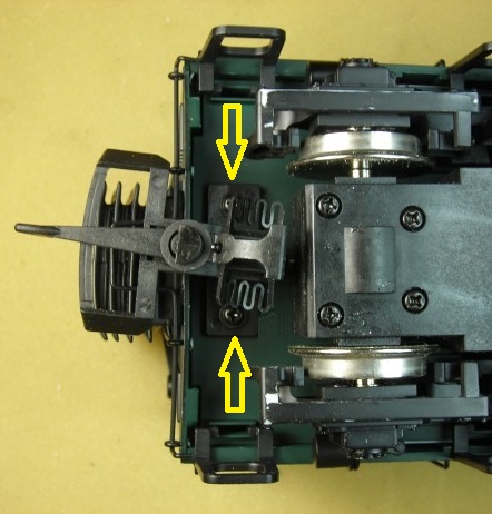
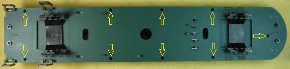
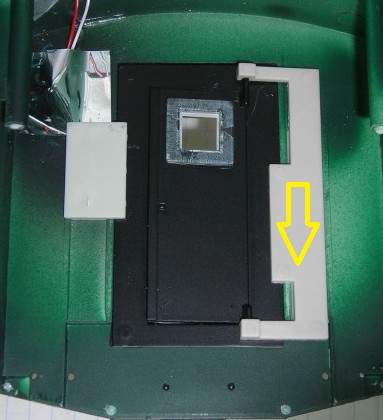
Place the locomotive on its side on a soft surface. Remove the leaf spring stirrups from the two upward facing side frames. Remove the screws outlined in yellow, and slip the side frames from the ends of the wheel axles. Fasten the screws back in the motor block A-frames so they don’t get lost or mixed up with others.
Unplug the four wires from each of the motor blocks. Remove the motor blocks, and wipe excess grease off the ends of the axles. Set the motor blocks aside for now.
Flip the locomotive over, and remove the leaf spring stirrups and screws from the remaining side frames. Fasten the screws back in the motor block A-frames so they don’t get lost or mixed up with others.
It is imperative that the track power wiring be removed to ensure the locomotive cannot pick up track power or feed battery power into the tracks. The result could be electronically catastrophic.
Unsolder all the wires from the tabs on the inside of all the side frames. Wipe the grease off the short black wires that ran between the tabs, and place them in a Ziploc bag labeled F3-A along with the road name and number of the locomotive.
Wipe the excess grease off the side frames. Pop the leaf spring stirrups back on, and set the side frames aside with the motor blocks for now.
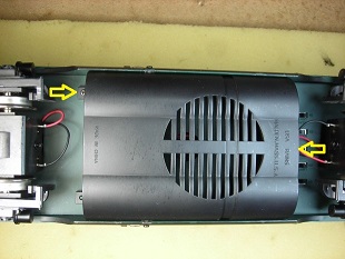
Place the locomotive upside-down on a foam slab or soft engine cradle, taking care not to damage the horns. There are nine screws holding the shell to the frame as shown in the next picture. These are hidden in deep burrows in the frame and will require a long Phillips #1 screwdriver to remove them. If you have trouble lifting them out, magnetize the screwdriver tip.
After removing the screws, carefully set the locomotive on its wheels beside the foam slab or soft engine cradle. Lift the shell from back to front just far enough to lay it beside the frame. Fasten the nine screws in the shell so they do not get lost or mixed up with others.
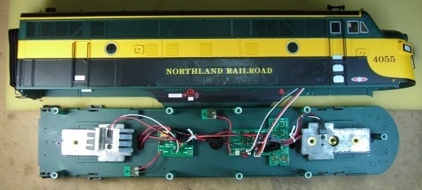
Remove the white cable ties from the wiring. Unplug the two white connectors for the front lights from the main circuit board. Set the shell aside for now.
Before going any further, inspect and repair if necessary all the places where the wires for the connectors are soldered to the main circuit board. Then place hot glue over all these places so the wires will not fray or break when the frame is being handled.
TRACK POWER WIRING
It is imperative that the track power wiring be removed to ensure the locomotive cannot pick up track power or feed battery power into the tracks. The result could be electronically catastrophic.
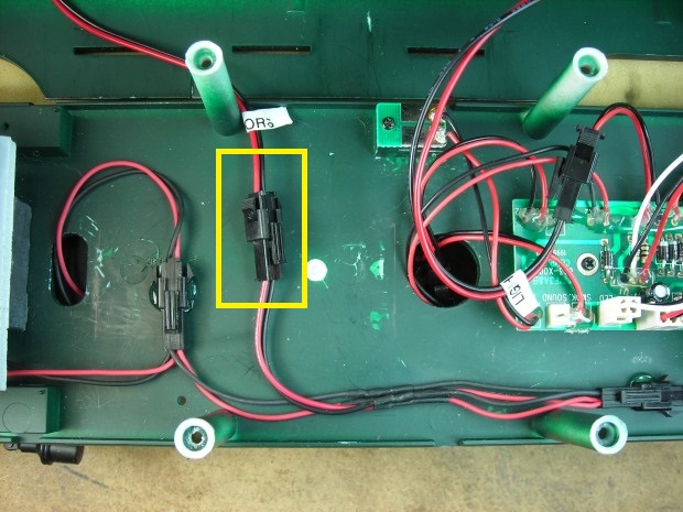
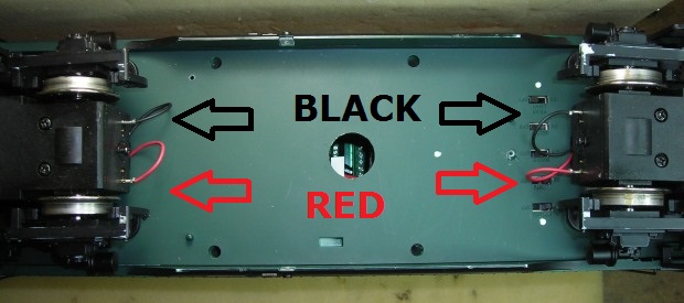
There are two sets of connectors whose wires were disconnected from each motor block. But only one connector from each motor block has two red wires and two black wires on it. Unplug these motor block connectors and set them aside for now as they will be used later. Set the frame aside for now.
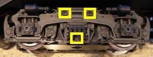
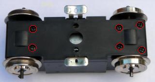
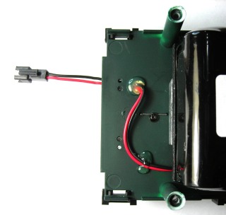
Place the motor blocks upside down. Remove the six screws (circled in red) from the bottom of each motor block and remove the bottom covers.
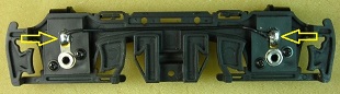
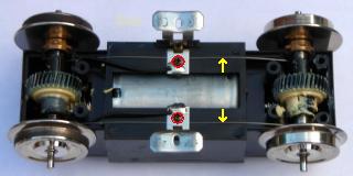
Remove the small screw (circled in red) from each track slider bracket. Remove the track sliders and springs. Remove the wire axle wipers (indicated with yellow arrows) sprung between the axles. Wipe the grease off the track sliders and wire axle wipers, and place them in the Ziploc bag. Fasten the chrome brackets back in place.
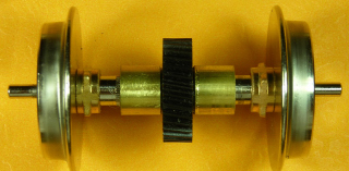
Check to see if any of the drive gear axle sleeves are split. You should not be able to gently turn any of the wheels with your fingers while holding the opposite wheel. If you can, the wheel will slip under load and may not stay properly gauged.
Although new axle assemblies are available from USA Trains, the damaged drive gear axle sleeves can be repaired with a collar of brass tube. There is an article on this web site that shows how this can be done. Just click on the link DRIVE GEAR AXLE SLEEVES REPAIR to access it.
If the axle sleeves are not cracked, ensure the drive gears and motor worm gears are suitably greased. Place the axle assemblies back in the motor block, ensuring the axle bushings are sitting flat in the grooves on the side of the motor block casings. If the drive gears are properly meshing with the motor worm gears, the wheels should not turn. Snap the bottom cover back on each of the motor blocks, and fasten each of them with six screws. Set the motor blocks aside for now.
SMOKE UNITS
The smoke units will be removed because they waste a lot of battery power, and the space in the top of shell will be used to mount the radio control receiver in a Plug and Play Board.
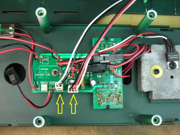
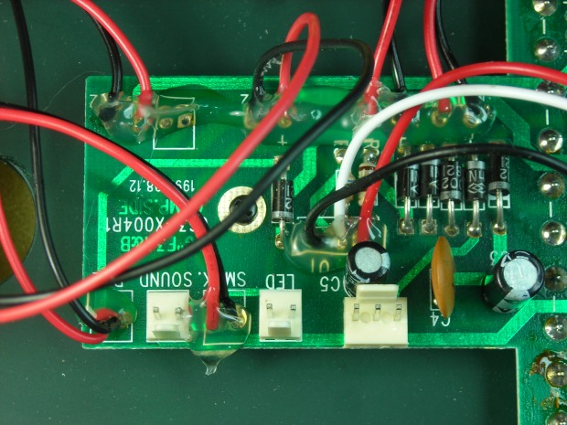
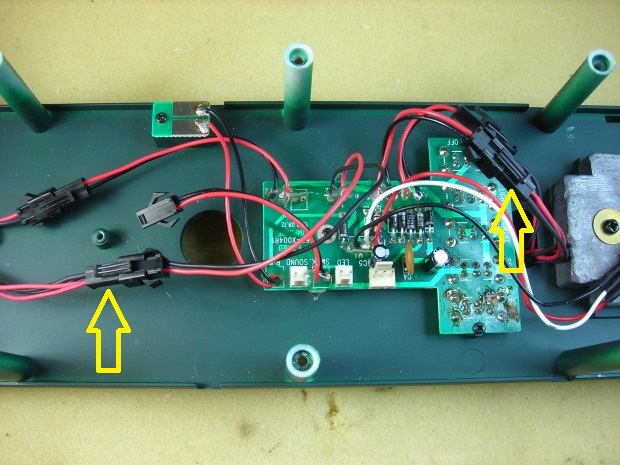
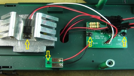
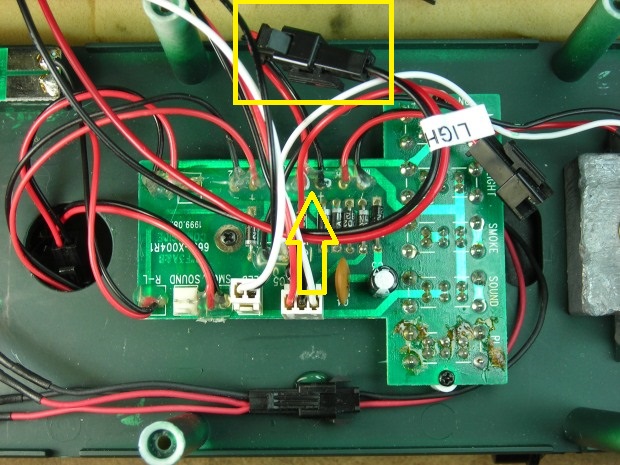
Remove the screw from the voltage regulator and heat sink on the rear weight. Remove the screw from the small circuit board next to the weight. Remove the two screws from the circuit board in front of the weight. Unplug the black connector that attaches the circuit board to the main T-shaped circuit board. Place the smoke board components and screws in the Ziploc bag.
Place the shell upside-down on a soft surface taking care not to damage the horns. Remove the four screws holding the smoke units to the shell. Pull the smoke unit connector off the post on the side of the shell. Place the smoke units in the Ziploc bag with the other components. Fasten the screws back in the shell, they are going to be used later.
Set the shell aside for now.
LITHIUM-ION BATTERY
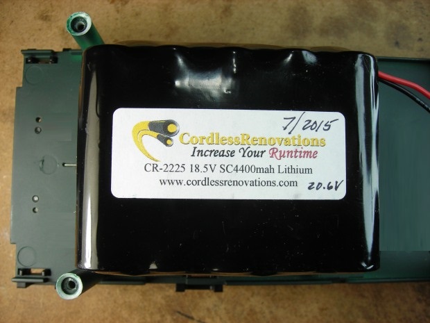
A Cordless Renovations CR-2225, 18.5 volt, 4400 milliamp hour, lithium-ion battery will be mounted on a piece of Elmer’s Craft Board fastened to the rear weight with double-sided tape. The battery is available from Remote Control Systems of New England. The craft board and tape were purchased at a local dollar store.
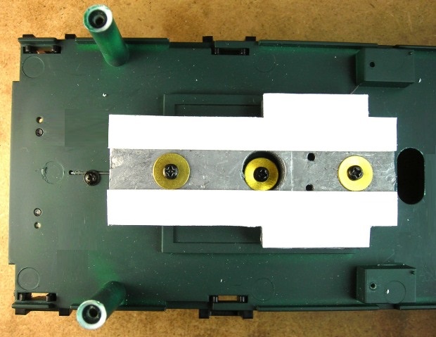
Remove the rear weight from the frame. Place the weight in a vice, and file the ridges off the top of the weight so the battery platform can sit flat on it. Clean the top of the weight with rubbing alcohol so the tape will adhere well.
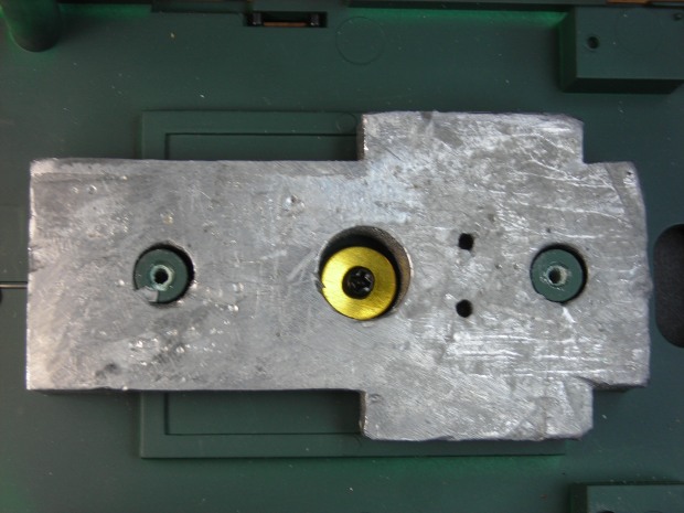
Fasten the weight back on the frame. Fasten a piece of double-sided tape to each side of the weight clear of brass washers. Remove the weight, place it upside-down on the floor, and step on it so the tape adheres well.
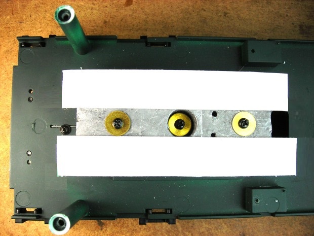
Place the weight upside-down on a cutting surface. Use a box knife to trim the access tape from the ends and sides. Fasten the weight back on the frame.
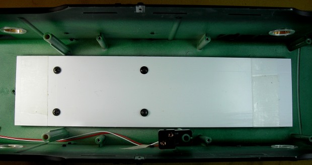
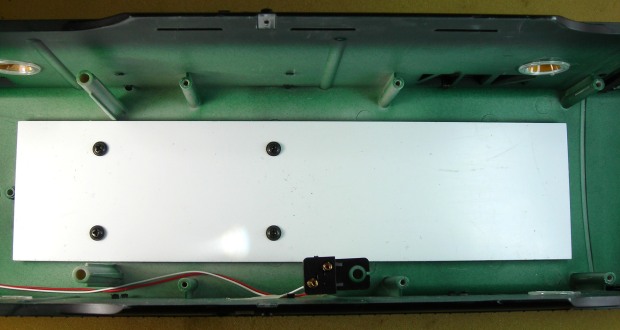
Cut a piece from the craft board 2 1/2 inches wide and 3 3/4 inches long. Fasten the piece to the weight ensuring the ends are flush with the ends of the weight and equally spaced from the sides of the frame.
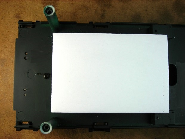
Place a strip of double-sided tape 1/2 inch in from each end of the craft board, and trim the edges with a box knife.
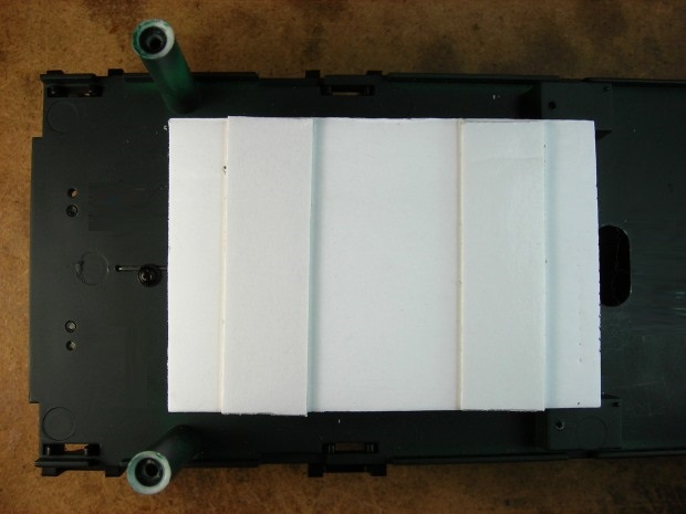
Fasten the battery to the board. Holding the bottom of the frame with one hand, use the other to push down on the battery to ensure it bonds the tape.
Set the frame aside for now.
ELECTRONIC COMPONENTS PLATFORM
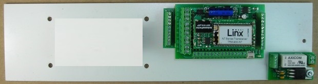
A 10 amp RailLinx 900 receiver, RCS Plug and Play Board, Phoenix Sound P8, and RCS Lights Relay Board will all be fastened to a styrene platform mounted in the top of the shell in place of the smoke units. All of these components are available from Remote Control Systems of New England. The space left for the installation and wiring of the sound board will be detailed in the second of these three articles.
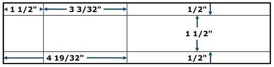
Cut two pieces, 2 1/2 inches wide by 10 inches long from a 1/16 inch thick sheet of styrene. Draw or lightly score with a fine awl on one of the pieces, lines 1/2 inch and 2 inches from one side. The lines must be exactly 1 1/2 inches apart. Using a small square, draw or lightly score lines across the long lines 1 1/2 inches and 4 19/32 inches from the end of the board. The lines must be exactly 3 3/32 inches apart. Use an awl to make an indentation at the 4 points where the lines intersect to guide a drill bit. Mark the indentations with a pencil point to make them easier to see.
Tape the two pieces together ensuring the ends and edges are flush, and the lines are facing outward. Drill a hole at the 4 points were the lines intersect with a 1/8 inch bit. Hold the sheets firmly or they may climb the bit and distort the shape and position of the holes.
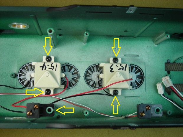
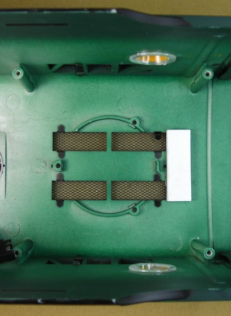
Remove the four screws that held the smoke units to the top of the shell. Use the screws to test fit the two pieces on the four posts in the center of the four fans. If they do not fit properly, enlarge the holes with a 5/32 inch bit.
Remove the two pieces, and remove the tape. Enlarge the holes in only one of the pieces with a 3/16 inch bit. Hold the sheet firmly or it may climb the bit and distort the shape and position of the holes. Test fit that piece on the shoulders of the four posts. If it fits on the shoulders of the posts properly, remove it and glue the other piece on top of it ensuring that the ends, edges and holes of the pieces line up properly.
When the glue has cured, fasten the platform on the shoulders of the four posts. Draw or score a line on the shell across the front of the platform. Remove the platform.
From the 1/16 inch thick sheet of styrene, cut 3 pieces 1 1/2 inches long by 1/2 inch wide. Glue the pieces together into a stack ensuring the ends and edges are flush. Apply a run of hot glue 1/4 inch behind the line on the shell. Fasten the stack between the front of the grills and the line as shown. Hot glue is required to fill the gap between the curved roof of the shell and the bottom of the stack.
Draw a line on top of the components platform 1/4 inch back from the front. Place a mark in the center of the line. Fasten the platform back on the four posts. Wrap vinyl tape 5/16ths of an inch from the tip of 3/32 inch bit. Drill a hole through the platform and into the stack no deeper than 5/16ths of an inch. Undo the screws and remove the platform.
Use one of the smoke unit screws from the frame that were placed in the Ziploc bag to tap threads in the hole in the stack. Do not force the screw too deeply or the stack may split. Remove the screw. Enlarge the new hole in the front of the components platform with a 1/8 inch bit. Fasten the platform back on the posts and stack with the five screws.
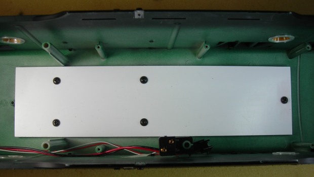
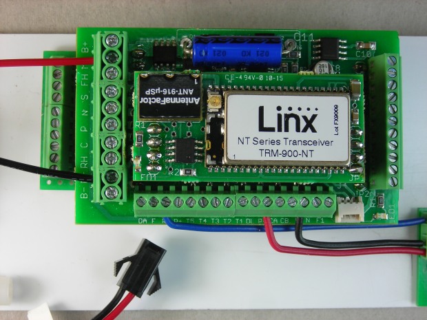
Plug a 10 amp RailLinx 900 Receiver into a RCS Plug and Play Board ensuring that the twelve pins at the front and eleven pins at the rear are properly seated in the headers. Set them on the components platform as shown. Draw a pencil line on the platform across the front and back of the PnP Board. Remove the PnP board with the receiver. Spread a line of hot glue 1/4 inch inside the lines on the platform. Line up the PnP board with the pencil lines and press it into the hot glue.
Fasten with hot glue an RCS Lights Relay Board on the bottom right corner of the components platform. The two-position screw terminal should face the front of the components platform as shown. The receiver and lights relay board will be wired after the battery switch is installed.
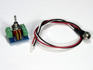
BATTERY SWITCH AND CHARGING JACK
The battery switch and charging jack is a RCS BIKU6 Installation Kit available from Remote Control Systems of New England.
The switch and charging jack will be mounted on a styrene sheet in place of the F3-A rear door.
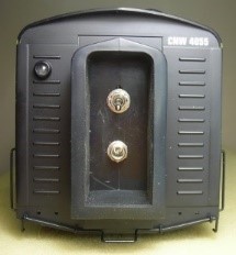
Remove the door by sliding the larger door bracket down from the shell. Set the bracket aside for now, it will be used later. Place the door frame, door and return spring in the Ziploc bag.
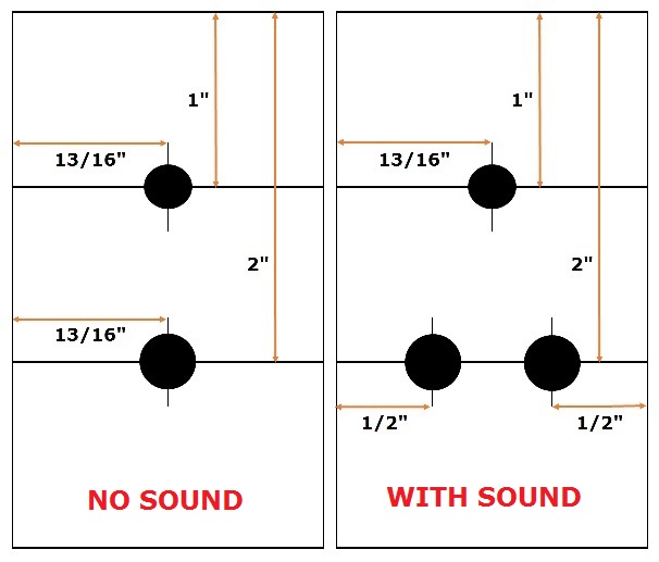
The replacement door is made from a piece of 1/16 inch thick styrene sheet. Score and snap a piece 1 5/8 inches wide by 3 1/6 inches long. Draw a line across the new door 1 inch from the top. Place a mark in the center of the line, and drill a 1/4 inch hole at the mark for the battery switch. Hold the door firmly or it may climb the bit and distort the shape and position of the hole.
Draw a second line across the new door 2 inches from the top. If a Phoenix Sound P8 is NOT going to be installed, place a mark in the center of the line. Drill a 5/16 inch hole at the mark for the battery charging jack. If a Phoenix Sound P8 is going to be installed later, place a mark on the line 1/2 inch in from each side of the door. Drill a 5/16 inch hole at each of the marks for the Phoenix Sound Programming jack and battery charging jack.
Paint the outside of the door black.
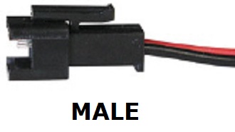
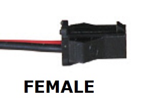
The male half of a 2-wire connector set will be used for the battery pack connection. The connector sets are available from All Electronics under catalog numbers CON-240.
CAUTION: The red and black wires on the connector sets sold by All Electronics are not usually positioned the same as the red and black wires on Cordless Renovation batteries. Compare the wiring to the female connector on the CR battery. If the wire colours do line up, click on the following link to see how to switch the positions of the AE Connector Set Wiring so that proper polarity is maintained.
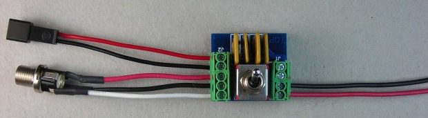
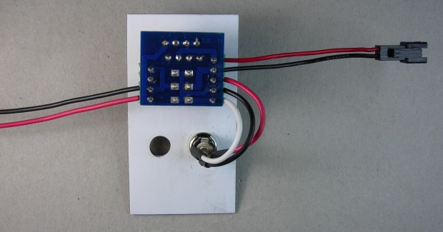
Trim the wires of the male half of a 2-wire connector to 2 1/2 inches long. Strip 1/4 inch of insulation off the ends of the wires. Fasten the red wire in the top of the 5-position terminal block as shown. Fasten the black wire in the next screw terminal down. This will be used to connect to the battery when the locomotive is re-assembled.
Trim the wires of the battery charging jack to 2 1/2 inches long. Strip 1/4 inch of insulation off the ends of the wires. Fasten the red wire in the middle of the 5-position terminal block as shown. Fasten the black wire in the next screw terminal down, and the white wire in the bottom screw terminal.
Cut a red and a black 22 AWG wire to 12 inches in length. Strip 1/4 inch of insulation off the ends of the wires. Fasten the red wire in the bottom of the 4-position terminal block as shown. Fasten the black wire in the next screw terminal up. These wires will be used to power the 10 amp RailLinx 900 receiver.
Remove the 8mm nut, lock and tab washers from the battery switch, leaving the second nut in place. Turn the second nut up until the yellow self-resetting fuses clear the inside of the door by 1/16 inch when the switch is inserted. Mount the switch so the self-resetting fuses face the top of the door.
Remove the 10mm nut and flat washer from the charging jack. Mount the jack in the bottom hole in the door. If a Phoenix Sound P8 is to be installed later, mount the charging jack in the hole on the right under the battery connector.
Fit the rubber diaphragm in place with the arched end up in the top of the shell. Spread a light coat of plastic compatible grease on the inside of the diaphragm so the new door will slide in without distorting the rubber. Push one side of the door under the smaller door bracket. The door should fit snugly in the channel in the shell from which the door frame was removed. Slide the larger bracket into the grove on the other side of the door as shown.
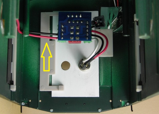
Run the 12 inch wires behind the posts on the side of the shell. Tape the wires so they will not show through the rear porthole or grill.
Like a light switch, the battery switch toggles up for the “POWER ON” position. NEVER INSERT THE CHARGING PLUG WHEN THE SWITCH IS IN THE “POWER ON” POSITION.
Flip the toggle down now to the “POWER OFF” and “BATTERY CHARGING” position.
LIGHTS RELAY BOARD
Remove the electronic components platform from the top of shell. Fasten the five screws back in the shell so they do not get lost or mixed up with others.
Strip 1/4 inch of insulation from the ends of the wires of the male half of a 2-wire connector. The connector sets are available from All Electronics under catalog numbers CON-240.
CAUTION: The red and black wires on the connector sets sold by All Electronics are not usually positioned the same as the red and black wires on Cordless Renovation batteries. Compare the wiring to the female connector on the CR battery. If the wire colours do line up, click on the following link to see how to switch the positions of the AE Connector Set Wiring so that proper polarity is maintained.
Fasten the red wire in the inside screw terminal of the 2-position terminal block on the lights relay. Fasten the black wire in the outside screw terminal. Print a small “LIGHTS” label, and fasten it around the wires near the connector.
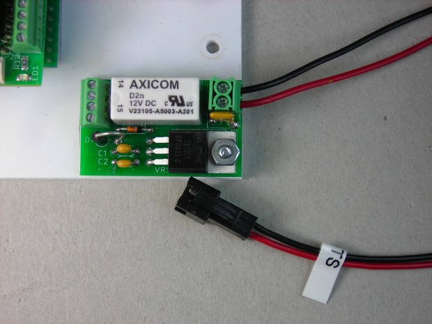
Cut a blue (or any colour other than red or black) wire to 2 3/4 inches long. Cut a red wire to 2 inches long, and a black wire to 1 3/4 inches long. Strip 3/16ths of an inch of insulation off both ends of the wires.
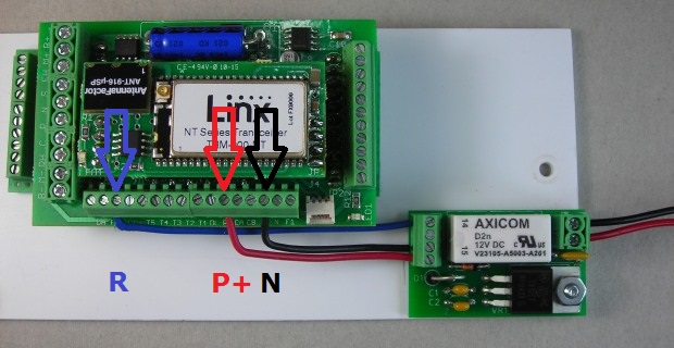
Bend the end of the blue wire and fasten it in the 3rd screw terminal from the LEFT on the side of the receiver labelled “R”. Fasten the other end in the outside screw terminal on the lights relay as shown.
Bend the end of the red wire and fasten it in the 6th screw terminal from the RIGHT on the side of the receiver labelled “P+”. Fasten the other end in the inside screw terminal on the lights relay as shown.
Bend the end of the black wire and fasten it in the 3rd screw terminal from the RIGHT on the side of the receiver labelled “N”. Fasten the other end in the screw terminal next the red wire on the lights relay as shown.
Remove the 5 screws from the shell and fasten the components platform back in place.
10 AMP RAILLINX 900 RECEIVER
Strip 1/4 inch of insulation of the end of the wires of the female half of a 2-wire connector. The connector sets are available from All Electronics under catalog numbers CON-240.
CAUTION: The red and black wires on the connector sets sold by All Electronics are not usually positioned the same as the red and black wires on Cordless Renovation batteries. Compare the wiring to the female connector on the CR battery. If the wire colours do line up, click on the following link to see how to switch the positions of the AE Connector Set Wiring so that proper polarity is maintained.
Fasten the red wire in the screw terminal labeled “M+” on the front of the receiver as shown. Fasten the black wire in the screw terminal labelled “M-“. Print a small “MOTORS” label, and fasten it around the wires near the connector.
Ensure the battery switch it toggled down in the “POWER OFF” position. Strip 1/4 inch of insulation off the end of the long red wire and long black wire from the battery switch. Fasten the red wire in the outside screw terminal labelled B+ on the front of the RailLinx 900 receiver. Fasten the black wire in the outside screw terminal labelled B-.

WIRING HARNESS FOR THE MOTORS
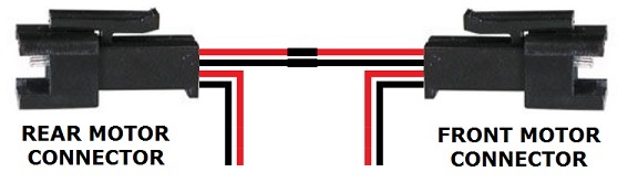
In a previous section entitled “Track Power Wiring” two 4-wire connectors were removed from the motor blocks. These are the redundant track power wiring connectors. Cut the wires on these to 2 1/2 inches in length. Strip 1/4 of an inch of insulation off the ends and twist the exposed wire so it does not fan out when soldered. Flux and tin the ends of the wires.
Slide a 3/4 inch piece of shrink wrap down a red wire and another piece down a black wire on one of these connectors. Solder and shrink wrap the red wire to a red wire on the other connector. Solder and shrink wrap the black wire to a black wire on the other connector.
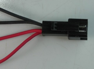
The male half of a 2-wire connector set will be used to connect the wiring harness for the motors to the receiver. The connector sets are available from All Electronics under catalog numbers CON-240.
CAUTION: The red and black wires on the connector sets sold by All Electronics are not usually positioned the same as the red and black wires on Cordless Renovation batteries. Compare the wiring to the female connector on the CR battery. If the wire colours do line up, click on the following link to see how to switch the positions of the AE Connector Set Wiring so that proper polarity is maintained.
Cut the wires of a 2-wire male connector to 2 1/2 inches in length. Strip 1/4 of an inch of insulation off the ends and twist the exposed wire so it does not fan out when soldered. Flux and tin the ends of the wires.
Slide a 3/4 inch piece of shrink wrap down the red wire and another piece down the black wire on the connector. Solder and shrink wrap the red wire to the red wire on the front motor connector. Solder and shrink wrap the black wire to the black wire on the front motor connector.
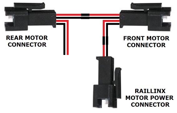
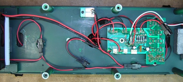
Plug the motor block wire connectors into the 4-wire connectors on the wiring harness. Lay the harness on the frame as shown and drop the motor block wires into their respective oval hole in the frame.
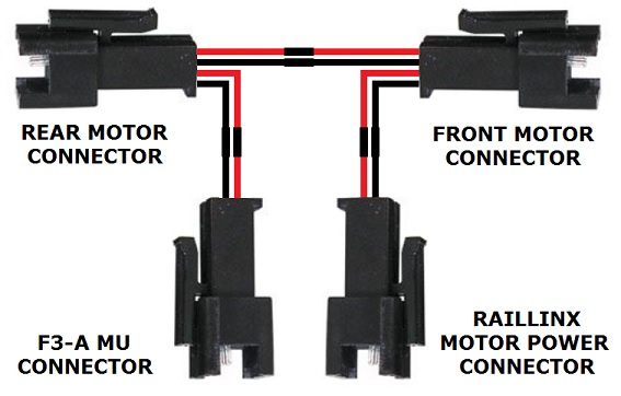
For this installation the remaining red wire and black wire on the rear motor 4-wire connector will be soldered to an MU connector to power a trailing F3-B locomotive. If this is not to be used, individually shrink wrap the red wire and the black wire on the rear motor 4-wire connector. Tape the wires out of the way on the frame.
If an MU connector is to be used, measure from the rear of the frame 1 inch forward between the holes for the coupler bracket and place a pencil mark. Drill a hole in the frame with a 1/8 inch bit.
The male half of a 2-wire connector set will be used as an MU connector. The connector sets are available from All Electronics under catalog numbers CON-240.
CAUTION: The red and black wires on the connector sets sold by All Electronics are not usually positioned the same as the red and black wires on Cordless Renovation batteries. Compare the wiring to the female connector on the CR battery. If the wire colours do line up, click on the following link to see how to switch the positions of the AE Connector Set Wiring so that proper polarity is maintained.
Pass the wires through the hole in the bottom of the frame. Leave 1 1/4 inch of wires showing between the back of the MU connector and the back of the frame. This will allow the MU connector to clear the rubber diaphragm when the shell is re-installed. Temporarily tape the wires to the bottom of the frame. Trim the wires so they will easily reach the free wires on the back of the motor wiring harness. Remove the tape.
Strip 1/4 of an inch of insulation off the ends and twist the exposed wire so it does not fan out when soldered. Flux and tin the ends of the wires.
Slide a 3/4 inch piece of shrink wrap down the red wire and another piece down the black wire on the connector. Solder and shrink wrap the red wire to the red wire on the rear motor connector. Solder and shrink wrap the black wire to the black wire on the rear motor connector.
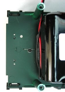
Check the distance between the back of the MU connector and the back of the frame. With the tab on the MU connector facing up, hot glue the wires at the hole for stress relief.
RE-ASSEMBLING THE LOCOMOTIVE
Remove the 9 screws from the shell and place them in a small container for now. Lay the shell on its side on a foam slab or soft engine cradle next to the frame. Plug the white connectors for the front lights back in the main circuit board.
Plug the connector attached to the CRS Lights Relay labelled “LIGHTS” into the connector labelled PICK1 on the main circuit board. Ignore that the wire colours do not line up, as the polarity will change with each change of direction.
Plug the connector attached to the 10 amp RailLinx 900 receiver labelled “MOTORS” into the connector on the wiring harness for the motors.
Check to ensure the battery switch is toggled down in the “POWER OFF” position. Plug the battery connector into the 2-wire connector fastened to the battery switch inside the back door. Run the wires behind the posts on the side of the shell. Tape the wires so they will not show through the rear porthole or grill.
Group the front wires together and rear wires together using the white twist ties or small cable ties. Place the shell back on the frame from back to front ensuring that none of the wires get pinched. Place the locomotive upside-down on a foam slab or soft engine cradle taking care not to damage the horns. Use the 9 screws to fasten the shell to the frame.
Remove the 12 screws from the motor block A-frames. Remove the leaf spring stirrups from the side frames. Apply a little grease to the ends of the wheel axles. Slip the side frames onto the axles. Use the 12 screws to fasten the motor blocks and side frames to the A-frames. The brass pins on the motor blocks should face the center. Push the leaf spring stirrups back on the side frames.
There should be a red and black wire hanging through an oval hole in each end of the frame. Push the metal terminals of these wires onto the outside brass pins on the motor blocks as shown. Usually opposing wire colours would be on the same side of the motor blocks because they would be fastened to two different PICK (track power pick-up) connectors on the main circuit board. But as they are both attached to PICK1, ensure both red wires are on the same side, and the black wires are on the other.
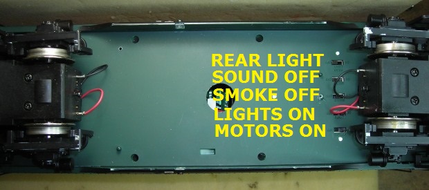
If this locomotive is to be MUed to another, turn the “REAR LIGHT” switch off. If not, leave it on. Turn the redundant “SOUND” and “SMOKE” switches off. Ensure the “LIGHTS” and MOTORS” switches are on.
Remove the two screws from the frame and fasten the fuel tank back on.
Remove the four screws from the ends of the frame and fasten the coupler and coupler brackets back on.
Place the locomotive on a length of track or set of testing rollers. Toggle the battery switch up to “POWER ON” position. All the lights should come on at full brightness. Turn the throttle/transmitter on by pushing the “STOP” key on the key pad. The throttle/transmitter will be pre-set to the default frequency setting “A1” and automatically linked to the receiver.

Push the “UP ARROW” key above the “STOP” key to accelerate and “DOWN ARROW” key under the “STOP” key to decelerate and stop. The “UP/DOWN” arrow key beside the “STOP” key is used to change direction. Test the locomotive to ensure the direction of the motors is synchronized with the direction of the headlights. Turn the throttle/transmitter off by simultaneously pushing the “AUX” and “STOP” keys. Toggle the battery switch down to the “POWER OFF/CHARGE” position.
Congratulations! You have successfully converted this locomotive to battery power and radio control.
If a Phoenix Sound P8 is to be added, read and follow the instructions in the second of these three articles.