
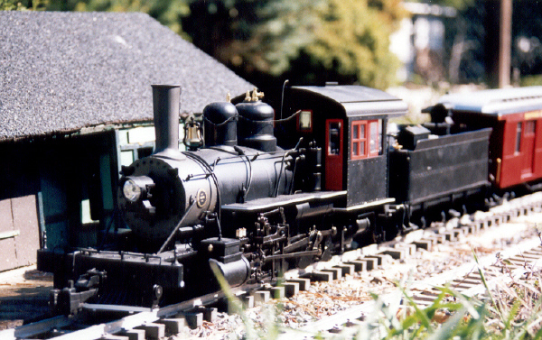
This article details a method used to convert a Bachmann 2-8-0 (Connie) steam locomotive from track power to on board: battery power, radio control, and sound using a 14.8 volt lithium-ion battery, an Aristo-Craft Revolution receiver, and a Phoenix Sound 2K2.
The article appears long because it is detailed and includes lots of pictures. But if you take your time and follow it step-by-step it is not difficult, and the results will be well worthwhile.
Nothing prevents the locomotive and tender from being restored to their original condition for re-sale at a later date, as any track power wiring removed will be stored intact in a labeled Ziploc bag.
Please read the article carefully, highlighting the components that are needed. Sources of supply are suggested for items not sold by your hobby suppliers. OVGRS members can purchase the required components by contacting Paul Norton.
LOCOMOTIVE TRACK POWER WIRING
It is imperative that the track power wiring be removed from the locomotive to ensure it cannot pick up track power or feed battery power into the tracks. The result could be electronically catastrophic.
Lay the locomotive on its side on a slab of foam or other soft surface. Remove the 4 small screws from the ash pan under the cab. Set the screws in the ash pan, and set it aside for a moment. Unplug the 2-wire, track power connector from the 2-pin header labeled “CON7” on the circuit board.
Refasten the ash pan back on the frame with the 4 small screws. That completes the isolation of the track power wiring in the locomotive. Place it back in its packaging for now.
TENDER TRACK POWER WIRING
Like the locomotive, it is imperative that the track power wiring be removed from the tender to ensure it cannot pick up track power or feed battery power into the tracks.
Remove the coupler cut bar from the back of the tender. Remove the water hatch from the top of the tender. Twist the brake wheel staff in order to remove the brake wheel from the front of the tender. Lift the wooden wall and coal spill free. Place all these parts in a Ziploc bag, and set them aside for now so they do not get lost or broken.
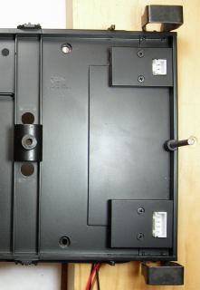
Place the tender upside-down on a soft engine cradle, or slab of Bachmann packing foam, taking care not to damage the rear light. Remove the 2 screws at the front of frame.
Carefully set the tender back on its wheels, and place it beside the work cradle. Lift the front end up and the tabs on the back of the tender body should come free from their holes in the frame. Set it on the work cradle beside the frame.
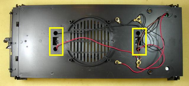
The rear light wires on the tender body are attached to two posts in the middle of the frame. Unsolder the black wire and the resistor on the red wire from their brass loop terminals. Fasten the 2 screws back in the tender body, and set it aside for now with the other parts in the Ziploc bag.
There are 4 track power wires coming up through 4 holes in the frame. Unsolder them from their brass loop terminals on the posts at the front of the frame.
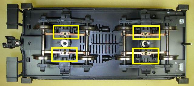
Turn the frame over. Place a finger of your left hand (right hand if you are left-handed) under one end of a truck bolster to continually hold a set of brake shoes in place. Remove the screw that holds the brake shoes in place with your other hand, and push the bronze axle wiper a bit so the screw can be re-inserted and tightened down. Repeat the process for the other three axle wipers.
Lift the axle wipers and draw their track power wires out of the 4 holes in the frame. Place them all in a Ziploc bag labeled “Connie” along with the road name and number.
Set the frame back on its wheels. Remove the 4 screws and unsoldered loops from the 4 posts, and place them in the labeled Ziploc bag.
That completes the removal of the track power wiring from the tender.
BATTERY CHARGING CONNECTOR
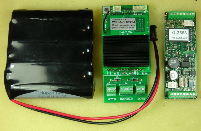
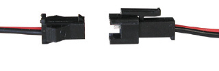
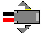
The female half of an All Electronics 2-wire connector set, shown on the left, will be used as a charging connector for the on-board battery. The connector set is available from All Electronics under catalog numbers CON-240.
CAUTION: The wires on the connector sets sold by All Electronics may not be positioned the same as the wires on the connectors of lithium-ion batteries and chargers. If not, click on the following link to see how to switch the positions of the AE Connector Set Wiring so that proper polarity is maintained.
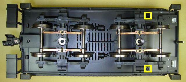
The battery charging connector will be mounted on the rear sill of the frame above the couple. To make it less conspicuous, trim the wings off and sand the sides smooth.
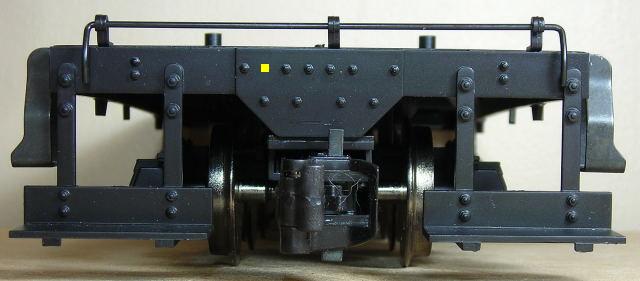
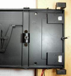
In the center of the sill on the back of the tender is a plate. In the top row of bolts measure half way between the two outside bolts on the left hand side of the plate and place a mark. Drill a hole on the mark through the plate and sill using a 1/8th inch bit in a pin vice.
With the notch of the charging connector facing up, feed the wires through the hole until the connector is snug against the pilot.

Turn the frame over and remove the rear truck. Draw the charging connector wires straight back and pass them through the hole to the right hand side of the bolster pin.
Remove the rear coupler. Remove the screw from the mounting platform, and slide a washer on the shaft. Fasten the screw back in. This will ensure the end of the screw will not protrude through the top of the frame and damage the battery. Re-install the coupler. Glue the tabs into the top of the bolster so they do not fall out again. Fasten the truck back on the frame.
Set the frame back on its wheels. That completes the installation of the battery charging connector. It will be connected when the battery switch is installed.
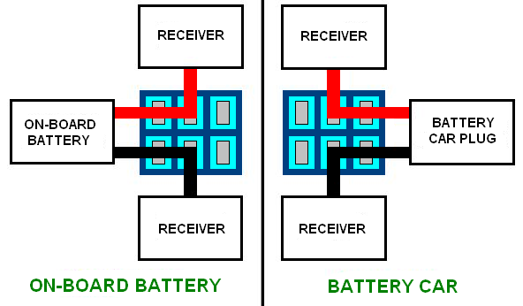
BATTERY CAR CONNECTOR
The owner of this locomotive wanted the option of being able to power it with either the on-board battery or a trailing battery car. The male half of an All Electronics 2-wire connector set, shown on the right, will be used as a battery car connector. The connector set is available from All Electronics under catalog numbers CON-240.
CAUTION: The wires on the connector sets sold by All Electronics may not be positioned the same as the wires on the connectors of lithium-ion batteries and chargers. If not, click on the following link to see how to switch the positions of the AE Connector Set Wiring so that proper polarity is maintained.
The battery car connector will be mounted in the top row of bolts between the two outside bolts on the right hand side of the plate. Measure half way between the two bolts and place a mark. Drill a hole on the mark through the plate and sill using a 1/8th inch bit in a pin vice.
Slide a half inch length of shrink wrap over the wires until it is snug against the connector. With the notch of the connector facing up, feed the wires through the hole until the end of the shrink wrap touches the sill.
Turn the frame over and remove the rear truck. Draw the wires straight back and pass them through the hole to the left of the bolster pin. Fasten the rear truck back on the frame.
Set the frame back on its wheels. That completes the installation of the battery car connector. It will be connected when the battery switch is installed.
SPEAKER
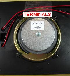
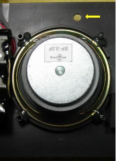
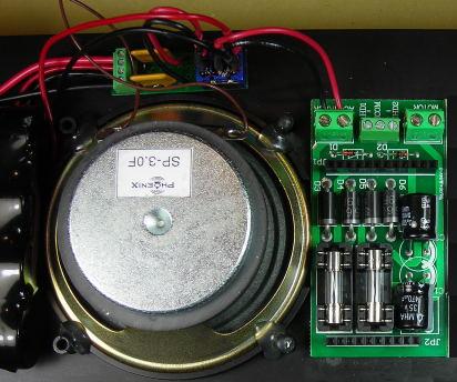
A Phoenix Sound three inch round speaker fits perfectly in the center of the tender. Place it so the terminals face the left hand edge of the frame. Hot glue it in place at each of the four posts.
That completes the installation of the speaker. It will be connected when the sound board is installed.
LITHIUM-ION BATTERY
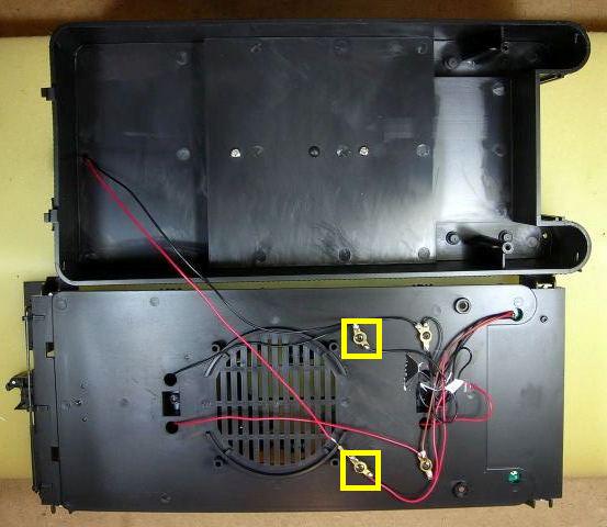
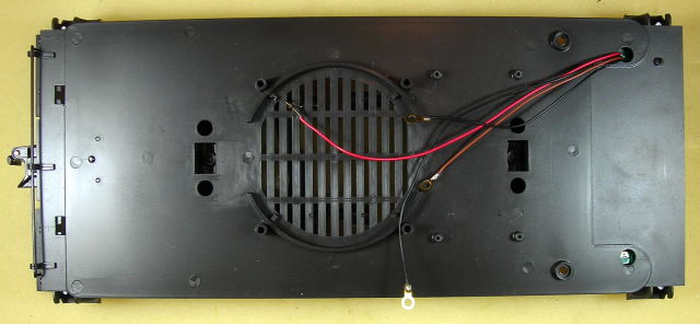
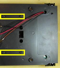
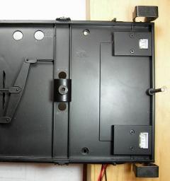
Cut two lengths of double-sided tape 2 1/2 inches long each. Apply the strips to the back of frame as shown in the following picture.
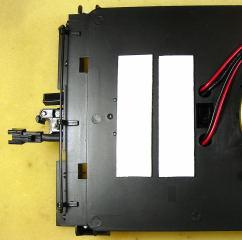
With the bottom snug against the round plastic speaker frame on the floor of the tender, fasten the battery to the double-sided tape.
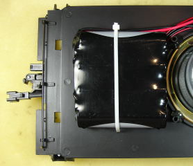
Over time the double-sided tape may dry out. To secure the battery, carefully drill a hole with a 1/8th inch drill bit in a pin vice on either side of it for a cable tie. Pass the tie through one hole, across the charging and power car connector wires on the bottom of the frame, up through the other hole, and around the battery and its wires. The tie should be snug, but not tight enough to damage the pack. That completes the installation of the battery. It will be connected when the battery switch is installed.
SELF-RESETTING POLYFUSES
Modern Aristo-Craft locomotives have self-resetting polyfuses to protect their electronics. In order to add them to this locomotive, a small circuit board will be built to hold them. The board will be fastened on the side of the frame with the battery switch.
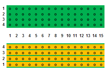
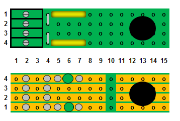
Cut or score and snap a small piece of straight trace perf board four traces wide by fifteen columns long. The straight trace perf board is available from All Electronics under catalog number ECS-4.
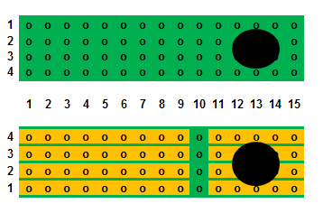
In column 13 between traces 2 and 3, drill a hole for the battery switch with a 1/4 inch bit. On the solder side of the board, cut open all 4 traces across column 10 with a razor saw, and clean it up with a small hobby file. The will isolate the metal parts on the switch from the rest of the circuit board.
Fasten a 4-position screw terminal block to the component side of the perf board with super glue. The pins of the block should be in column 2 and the openings for the wires should face out.
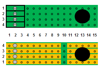
Flip the perf board over and solder the pins of the terminal block to the board. A good soldering iron of at least 40 watts and thin solder wire will be required. The pins and traces must be properly fluxed and heated, before the solder is added and allowed to flow.
The terminal block is manufactured by Phoenix Contact and is available from Mouser Electronics under the manufacturer’s part number 1725672 for the 4-position version.
Screw terminals 1 and 4 will be used for the battery wires, and terminals 2 and 3 for its charging connector wires. To allow the battery charger to work, trace 1 must be connected to trace 2, and trace 3 must be connected to trace 4. Strip the insulation off a couple of inches of 22 gauge solid core wire. Cut the wire in two, and bend 2 jumpers that will fit across traces 1 and 2, and traces 3 and 4 in column 4.
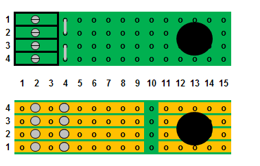
Flip the perf board over. Solder the jumpers to the board, and trim off any excess wire.
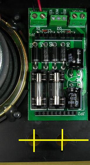
Flip the board back over and install the leads of a 2.5 amp polyfuse in columns 5 and 7 of trace 1. Flip the board over. Solder the leads to the board, and trim off any excess leads. Using a 1/8 inch drill bit in a pin vise, break open trace 1 between the leads of the polyfuse as indicated with the big green dot in column 6.
Flip the board back and install the leads of a 2.5 amp polyfuse in columns 5 and 7 of trace 4. Flip the board over. Solder the leads to the board, and trim off any excess leads. Using a 1/8 inch drill bit in a pin vise, break open trace 4 between the leads of the polyfuse as indicated with the big green dot in column 6.
The polyfuses are available from Mouser Electronics under the manufacturer’s part number 30R250UU. OVGRS members can purchase the fuses by contacting Paul Norton.
Cut a 3 inch length of 22 gauge red wire and a 3 inch length of 22 gauge black wire. Trim 1/8 of an inch of insulation off one end of both wires. Place the end of the red wire in column 9 of trace 1, and turn the board over. Solder the red wire to the board, and flip it back over. Place the end of the black wire in column 9 of trace 4, and turn the board over. Solder the black wire to the board. Clean the solder side of the board with flux remover and an old toothbrush.
These wires will be used to connect the circuit board to the battery switch when it is installed.
BATTERY SWITCH
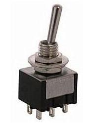
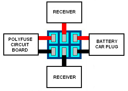
As this installation will have two sources for battery power, a double-pole double-throw (DPDT) center-off switch is needed to toggle the receiver and sound board between the on-board battery and the trailing battery car.
The DPDT center-off switch is available from All Electronics under catalog number MTS-12.
The switch and polyfuse circuit board will be mounted on the left hand side of the frame near the speaker terminals.
Tape the battery, charging connector, and trailing power car connector wires back out of the way. Place a mark 5 1/2 inches from the front of the tender floor, and 1/2 inch in from the left edge. On the mark, drill a hole using a 1/8 inch drill bit in a pin vice.
The hole has to be enlarged to 1/4 of an inch for the battery switch. Unfortunately the wide frame on narrow gauge trucks makes it unstable for drilling such a large hole. Flip the frame over and slide a 2 x 4 block under the front of the frame until it touches the posts for the mounting screws. The block and the flat top of the Phoenix Sound speaker will provide a more stable platform for drilling. Drill slowly in steps. Hold the frame firmly so it does not bend or climb the bit making an oblong hole.
Set the frame back on its wheels. Remove the top nut and the washers from the switch, but leave the last nut in place. Place the switch through the hole in the front of the polyfuse circuit board, and mount it in the hole on the side of the frame using the second nut. The screw terminal block on the polyfuse circuit board should face the battery.
CAUTION: Do not let the battery wires touch each other, or anything metal at the same time. Ensure the battery switch is in the center-off position. Trim the black wire on the battery to a length that will reach inside screw terminal 4 on the polyfuse circuit board. Strip 3/16ths of an inch of insulation of the end of the black wire and fasten it under screw terminal 4.

Trim the red wire on the battery wire to a length that will reach inside screw terminal 1 on the polyfuse circuit board. Strip 3/16ths of an inch of insulation of the end of the red wire and fasten it under screw terminal 1.
The battery charging connector wires should be the longer of the two remaining sets of red and black wires protruding from under the battery. Trim them to a length that will reach inside screw terminals 2 and 3 on the polyfuse circuit board. Strip 3/16ths of an inch of insulation of the end of the black wire and fasten it under screw terminal 3. Strip 3/16ths of an inch of insulation of the end of the red wire and fasten it under screw terminal 2.

Strip 3/16ths of an inch of insulation off of the ends of the wires of the male half of an All Electronics connector set. Plug the male connector into the battery charging connector on the back of tender. Fasten the leads of a voltage meter across the ends of the male connector wires. Toggle the battery switch forward to test that the polarity of the battery charging connector is correct. Toggle the battery switch to its center-off position, and remove the male connector and voltage meter.
If the polarity was not correct, reverse the wires in screw terminals 2 and 3 on the polyfuse circuit board, and re-test the battery charging connector. Toggle the battery switch to its center-off position, and remove the male connector and voltage meter.
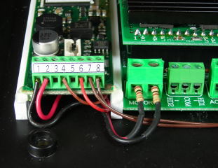
Strip 3/16ths of an inch of insulation off of the ends of the red and black wires on the front of the polyfuse circuit board. Slip a 1/2 inch length of shrink wrap down each the wire. Flux and solder them to the left hand terminals of the DPDT switch as shown in the following wiring diagram. Push the shrink wrap over the soldered joints and switch terminals, and heat it.
Cut a 3 inch length of red wire, and a 3 inch length of black wire. Strip 3/16ths of an inch of insulation off of both ends of the wires. Flux and solder one end of them to the center terminals of the DPDT switch as shown in the wiring diagram. Slip a 1/2 inch length of shrink wrap on each the wire. Push the shrink wrap over the soldered joints and switch terminals, and heat it. These wires will be used to connect the battery switch to the “AC-TRACK” screw terminals on the (non) Plug and Play Board when it is installed.
The trailing battery car connector wires are the remaining set protruding from under the battery. Slip a 1/2 inch length of shrink wrap down each wire. Strip 3/16ths of an inch of insulation of the end of the wires, and solder them to the right hand terminals of the DPDT switch as shown in the wiring diagram. Push the shrink wrap over the soldered joints and switch terminals, and heat it.
Ensure all the wires on one side of the battery switch are red, and black on the other. Attach the leads of a voltage meter across the ends of the red and black wires soldered to the center terminals of the battery switch. Toggle the battery switch forward and test to ensure the polarity of the on-board battery is correct. Leave the voltage meter in place, but toggle the battery switch back to its center-off position.
Plug a trailing battery car (or battery) into the connector on the back of tender. Toggle the battery switch backwards, and test to ensure the polarity of the battery car connector is correct. Toggle the battery switch to its center-off position and remove the voltage meter.
That completes the installation of the battery switch.
REVOLUTION RECEIVER
The Revolution receiver will be mounted in a (non) Plug and Play Board (CRE 57078) in front of the speaker. This will require the removal of the four posts at the front of the frame. Fasten pieces of vinyl or masking tape on the floor of the tender around the four posts to protect it from getting scratched. Cut the posts flush with the floor. Remove the tape.
Fasten the double-sided tape provided across the bottom of the Plug and Play Board. With the screw terminals facing the battery switch, place the board snug against the round plastic speaker frame on the floor of the tender. Press on the board to fasten the double-sided tape firmly to the frame.
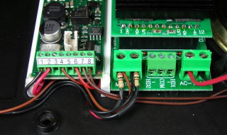
Fasten the black wire soldered to the center terminal of the battery switch in the outside screw terminal of the adapter board labeled “AC-TRACK”. Fasten the red wire soldered to the center terminal of the battery switch in the inside screw terminal. That completes the wiring of the battery switch.
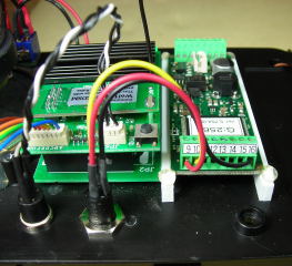
The remote linking button and sound board programming jack will be mounted near the edge of the frame behind the PnP board. Draw a pencil line behind the board, 1/2 of an inch in from the side of the frame. Place marks on the line 3 3/4 and 4 1/2 inches from the front of the tender floor. At each of the marks, drill a hole using a 1/8 inch drill bit in a pin vice. Erase the pencil line.
The holes have to be enlarged to 5/16ths of an inch for the remote linking button and programming jack. Unfortunately the wide frame on narrow gauge trucks makes it unstable for drilling such large holes. Flip the frame over and remove the front truck. Slide a 2 x 4 block under the front of the frame until it touches the posts for the mounting screws. The block and the flat top of the Phoenix Sound speaker will provide a more stable platform for drilling. Drill slowly in steps. Hold the frame firmly so it does not bend or climb the bit making oblong holes.
Trim the wires on the programming jack to 3 inches long. Set the excess wires aside for now. Remove the shrink wrap surrounding all three of the programming jack wires, but leave the smaller shrink wrap covering the individual wires and the solder joints on the terminals. Fasten the Phoenix Sound programming jack in the hole closest to the front of the frame.
Cut the wires for the remote linking button 4 inches from the small white connector. Cut the shrink wrap off the terminals of the button, and unsolder the wires. Set the excess wires aside for now. Solder and shrink wrap the two black wires on the connector to one side of the switch, and the white wire to the other. Fasten the button in the open hole.
Glue the tabs into the top of the bolster so they do not fall out again. Fasten the truck back on the frame. Set the frame back on its wheels.
Plug the receiver into the PnP Board ensuring all the pins are properly installed in the front and rear headers. Plug the remote linking button connector into the 3-pin header on the back of the receiver. Plug the connector with the 7 trigger wires into the 7-pin header beside it.
Raise the antenna! That completes the installation of the receiver. The wiring of the PnP board will be completed after the sound board is installed.
PHOENIX SOUND 2K2
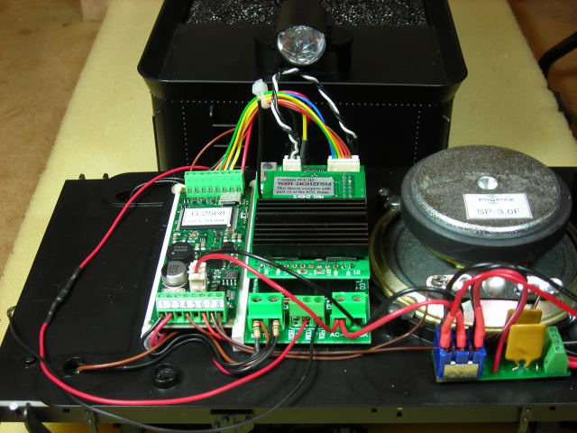
The Phoenix Sound 2K2 will be fastened on styrene strips beside the receiver. The strips allow wires to pass under the board and air to cool the bottom components.
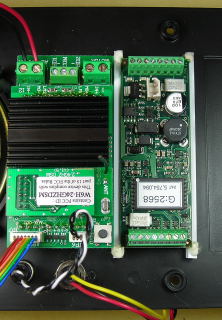
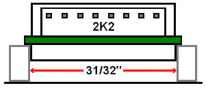
From a 1/8 x 1/4 inch styrene strip, cut two pieces 3 1/8th inches long. Cut two more pieces exactly 31/32nds of an inch long. Use CA (super glue) to fasten one of the long pieces on edge, butting up against edge of the PnP Board.
Using the small pieces as spacers, fasten the other long piece on edge to the frame exactly 31/32nds of an inch from the first. When the glue has dried, remove the spacers.
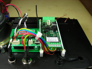
Place the sound board on top of the two styrene strips mounted on the frame, with terminal 1 to 8 facing the battery switch edge of the frame. The components on the bottom of the sound board should sit in between the strips, while the 2K2 circuit board should sit on top of the inside edges. Fasten the corners of the sound board to the strips with small dabs of hot glue.
That completes the installation of the Phoenix Sound 2K2. Next the wiring for the receiver and the sound board will be connected.
WIRING THE RECEIVER AND SOUND BOARD
There are still a lot of wires to be connected to the receiver and sound board, but the wiring will be done in small steps with accompanying pictures as a guide.
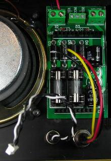
Strip 3/16ths of an inch of insulation off the ends of all three wires on the sound board programming jack, and tin them. Fasten the red wire in screw terminal 9, the yellow in 10, and the black in 16.
Cut ONLY the blue, green, yellow, and orange receiver trigger wires to 3 1/2 inches in length. Strip 3/16ths of an inch of insulation off the ends, and tin them. Fasten the blue wire in 2K2 screw terminal 11, yellow in terminal 12, green in terminal 13, and orange in terminal 14.
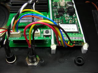
Pass the red and brown trigger wires under the 2K2 to the other side of the frame. They will be dealt with later.
Cut the black (ground) wire off the receiver trigger wire connector. Cut the wire in two. Strip 1/8th of an inch of insulation off one end of the wires, and tin them.
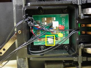
Under the right front edge of the tender is a circuit board with a 2-pin header for the chuff activation connector. Tip the frame on its side and remove the two screws holding the cover over the 2-pin header. Remove the cover and the circuit board.
Solder the one of the black wires to each of the center traces on the circuit board. Pass the wires through the hole in the frame, and place the circuit board back between the two posts. Fasten the cover back on with the two screws.
Set the frame back on its wheels. Strip 3/16ths of an inch of insulation off the ends of the black wires, and tin them. Fasten them in 2K2 screw terminals 15 and 16. Tuck their excess wiring under the sound board out of the way of the tender body mounting post and screw.
Gather the 3 programming jack wires and 6 receiver trigger wires together with a small cable tie so they are out of the way of the tender body mounting post and screw. Trim the excess cable tie. That completes the wiring on the right hand side of the frame.
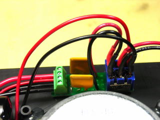
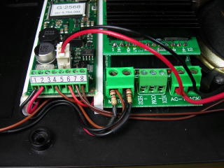
Turn the frame around so the PnP board screw terminals are accessible. Cut 4 inches off the ends of the red and brown trigger wires that were previously passed under the sound board. Strip 3/16ths of an inch of insulation off the ends of wires and tin them. Fasten the brown wire in 2K2 terminal 4 and the red in terminal 6. Tuck the excess wire under the sound board out of the way of the tender body mounting post and screw.
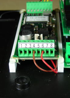
To wire the speaker some left over Phoenix Sound brown wire was used in this installation, but any small gauge wire like that cut from the remote linking button could be used. Strip 3/16ths of an inch of insulation off one end of the wires and tin them. Solder them to the speaker terminals. Run the wires past the front of the PnP Board, and trim them so they will reach inside the sound board terminals 7 and 8. Strip 3/16ths of an inch of insulation off the ends of the wires and tin them. Fasten them in the screw terminals 7 and 8.
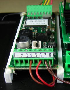
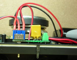
Trim the leads of two 100 ohm, 1/4 watt resistors to 1/4 of an inch. Phoenix Sound recommends they be added when using other than the 3.6 volt battery supplied for track power to power the 2K2.
Strip the shrink wrap off the excess wires cut from the programming jack. Solder a resistor to the tinned end of each of the red and black wires. Slip 1/2 an inch of shrink wrap up each wire and over the solder joint. Heat the shrink wrap.
Fasten the free end of the resistor soldered to the red wire in the outside screw terminal on the Plug and Play Board labeled “MOTOR”. Fasten the free end of the resistor soldered to the black wire in the inside screw terminal. Cut the wires to 3 inches in length. Strip 3/16ths of an inch insulation off the ends of the wires and tin them. Fasten the black wire in 2K2 terminal 1 and the red in terminal 2. Tuck the excess wire under the sound board out of the way of the tender body mounting post and screw.
There are four wires soldered to a 4-pin header under the front left hand side of the frame. The longer red and black wires were used to power the rear light, but in this installation it will be powered and controlled from the receiver. Tip the frame on its side and remove the two screws holding the cover over the 4-pin header.
Unsolder the longer red and black wires from the small circuit board, and set them aside for now. Fasten the cover back on with the two screws.
The shorter brown and black wires soldered to the small circuit board were used to provide track power to the locomotive. In this installation they will provide battery power from the receiver to control the locomotive. Unsolder the brass loop connectors from these wires, and place them in the Ziploc bag. Trim the soldered tips off both wires. Strip 1/4 of an inch of insulation off the ends, and tin them. These wires will be inserted in the screw terminals on the PnP board labeled “MOTOR” with the 2K2 motor speed (voltage) sensing wires. Fasten the black wire in the inside screw terminal on the PnP board labeled “MOTOR” with the black of wire from 2K2 screw terminal 1. Fasten the brown wire in the outside screw terminal on the PnP board labeled “MOTOR” with the red of wire from 2K2 screw terminal 2.
Just behind sound board screw terminals is a 2-pin header for the 3.6 volt battery that Phoenix Sound provides for track power. But in this installation the 2K2 will be powered from the on-board battery or the trailing power car. A small battery connector will be used to connect the sound board to the “AC-TRACK” terminals of the PnP board. The small battery connector is available from All Electronics under catalog numbers SBC-2.
Trim the wires on the connector to 3 inches in length. Strip 3/16ths of an inch of insulation off the ends of the wires, and tin them. Plug the connector into the 2-pin header on the 2K2. Fasten the black wire in the outside screw terminal of the adapter board labeled “AC-TRACK” with the matching black wire from the battery switch. Fasten the red wire in the inside screw terminal with the red wire from the battery switch.
The wires fastened to the rear light are too short to reach the screw terminals on the PnP Board labeled “HD1 and HD COM”. Unsolder the brass loops from the wires removed from the small circuit board at the front of the frame, and cut the soldered tips off the ends of the wires. Strip 3/16ths of an inch insulation off both ends of the wires, and tin them.
Unsolder the brass loop from the black wire attached to the rear light, and cut the soldered tip off the end of the wire. Strip 3/16ths of an inch of insulation off the end of the wire and tin it.
Solder the two black wires together. Slip 1/2 inch of shrink wrap over the wires and solder joint, and heat it. Solder the red wire to the end of the resistor on the red rear light wire. Slip 1 1/2 inches of shrink wrap over the resistor and solder joints, and heat it.
Fasten the end of the red rear light wire in the screw terminal on the PnP Board labeled “COM”. Fasten the end of the black rear light wire in the screw terminal on the PnP Board labeled “HD1”. Set the tender body beside the frame so you can see the rear light.
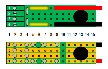
The following is a diagram of the wiring in the tender. Print it off in colour, and highlight every screw terminal where the wiring is the correct colour and connected properly.
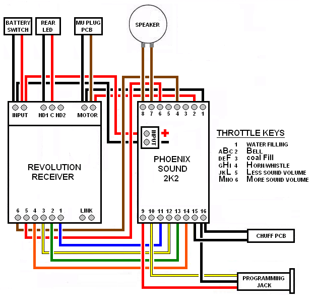
That completes the wiring of the tender!
Remove the 2 screws from the tender body, and place the body on the frame taking care not to pinch the rear light wires. The tabs on the back of the tender body fit into the holes in the back of the frame, and the front will snap into place over the frame. Carefully turn tender over and place it on the engine cradle. Use the 2 screws to fasten the tender body to the frame. Set the tender on its wheels.
Fasten the coupler cut bar to the back of the tender, the water hatch to the top, the coal spill, wooden wall, and brake wheel back to the front.
Next the Revolution receiver will be programmed and the 2K2 sound board tested.
CHARGING THE BATTERY
Make sure the battery switch is in its center-off position. If the battery has not been charged, plug an appropriate lithium-ion battery charger into the charging connector on the back of the tender and top it up.
PROGRAMMING THE RECEIVER
To program the receiver follow the instructions in the Installation and Operation Manual for the Revolution Train Engineer on the CD that came with the set. The Revised Manual and other information is also available on the Aristo-Craft web site as an Adobe pdf file. To read or download the revised manual, click on the link.
Set the locomotive and the tender on a piece of track. Plug in the two connectors between the locomotive and tender. Toggle the battery switch forward to the run position, and program the receiver.
Test to ensure the motor, sound, and lights respond properly to the throttle, and that the lights and motor direction are in synch. After testing, return the battery switch to its center-off position.
Congratulations! You have successfully installed lithium-ion battery power, Revolution radio control, and Phoenix sound in your Bachmann 2-8-0 Consolidation (Connie).
1 comment
What sound file did you use for the 2-8-0?