
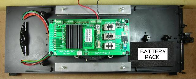
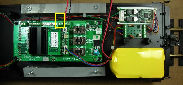
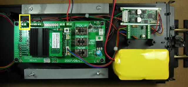
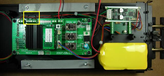
This article details a method used to install a Phoenix Sound P8 in a Battery Powered and Radio Controlled Bachmann K27. If the instructions from the previous article were followed, the tender frame should look like the following picture, except there will be a battery pack on the bottom right corner.
Phoenix Sound provides a momentary switch with the P8 to raise and lower the sound volume. But hiding the switch so it does not alter the appearance of the locomotive usually means it cannot be accessed while operating. Fortunately Phoenix Sound has designed a simple circuit that allows the volume to be raised and lowered while operating the locomotive using two trigger keys on the Revolution throttle.
Bachmann uses optical sensors in the cylinders of their K27 to trigger sound boards to produce steam engine chuff sounds. But these sensors generate a short positive pulse which is not compatible with the P8 sound board. Fortunately Phoenix Sound has designed a simple circuit that allows the Bachmann optical sensors to trigger the P8 chuff sounds.
This article shows how to assemble both these circuits on a small circuit board. Apart from basic soldering skills, no knowledge of electronics is required.
The screw terminals on this small circuit board are used to fasten the 14 wires between the P8 sound board and Revolution receiver needed to activate the chuff, whistle, bell, sound volume up, sound volume down, and one other sound function of your choice. The result is a neat and organized installation.
Sources of supply and part numbers are provided for all the items required to assemble the circuit board. OVGRS members can purchase all the electronic components by contacting Paul Norton.
Please read this article carefully. It appears long because it detailed and includes a lot of pictures; but if you take your time and follow the step-by-step directions it is not difficult. As sound adds an extra level of realism and enjoyment to this fine locomotive, the results are well worthwhile.
Bachmann placed all the required electronics in the tender of the K27, so the locomotive itself will not be altered in any way during the installation of the sound board. Furthermore, nothing in this installation prevents the tender from being returned to its original condition for re-sale at a later date.
OPENING THE TENDER
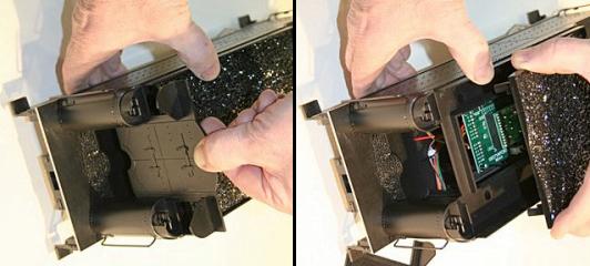
If the pin in the previous article has been installed, use it to lift the coal load. If not, pull out the coal doors panel, and remove the coal load.
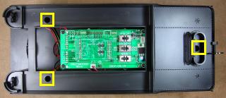
Use a Phillips, number 2, screwdriver to remove the three screws holding the tender body to the frame.
Unfasten the red and black battery switch wires in the screw terminals on the side of the PnP circuit board. Unplug the battery pack connector from the battery switch connector.
Put the coal doors panel and coal load back on the tender body, and set it aside for now so it does not get damaged. Fasten the three screws back in the frame so they do not get lost or mixed up with others.
PHOENIX SOUND SPEAKER
Use a Phillips, number 2, screwdriver to remove the four screws holding the Plug and Play (PnP) circuit board to the frame. Move the board enough to access the location for the speaker.
Remove the four screws holding the speaker brackets to the frame. Set the circle of foam aside. Use the screws, and if necessary the speaker brackets, to install a 3 inch round speaker to the frame.
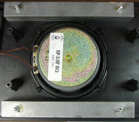
In this installation a Phoenix Sound 6 ohm speaker with tabs (SP-3.0F) was used. The four tabs on the speaker eliminated the need for the brackets, and the holes in the tabs lined up perfectly with the threaded holes in the frame.
Although this speaker produces tremendous sound, the large magnet rubbed against a capacitor on the bottom of the PnP circuit board. To solve the problem the capacitor was moved to the frame.
CAUTION: This capacitor is polarized and proper polarity must be maintained. The PnP circuit board is clearly marked with plus and minus signs for this purpose. Before unsoldering the capacitor place a black mark next to the negative lead.
Unsolder the capacitor from the PnP circuit board. Solder and shrink wrap a black wire to the negative lead, and red wire to the positive lead. The wires should be long enough so the board could be lifted after the capacitor is fastened to the frame in front of the speaker.
Solder the wires to the bottom of the PnP circuit board using the markings on the board as a guide. Place a dab of hot glue on the frame in front of the speaker and use it to secure the capacitor. Use the four screws in the small container to fasten the PnP circuit board back on its posts.
INTERFACE BOARD
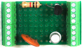
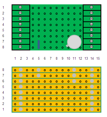
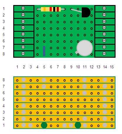
An interface board will be assembled to hold the P8 sound volume control circuit (top), and the optical chuff sensors activation circuit (bottom).
It is made from a perf board available from All Electronics under catalog number ECS-4. Score both sides of the perf board and snap off a piece 8 traces down by 15 columns across. Sand the edges smooth.
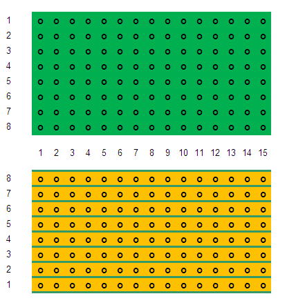
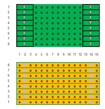
Fasten 8-position screw terminal blocks, or any combination of terminal blocks that will cover all 8 traces, to each end of the component (green) side of the perf board with super glue. The pins of the blocks should be in columns 2 and 14, and the openings for the wires should face out.
Flip the board over. Solder the pins of the screw terminal blocks to the board.
The terminal blocks are manufactured by Phoenix Contact and are available from Mouser Electronics under the manufacturer’s part number 1725711 for the 8-position version.
CHUFF ACTIVATION CIRCUIT
The chuff activation components will now be added to the circuit board. The components used are a 2N2222 or equivalent transistor, and a 0.1uf capacitor. The transistor and capacitor can all be purchased from Mouser Electronics under the part numbers 511-2N2222A and 81-RDEF51H104Z0K103B respectively.
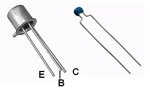
The 2N2222 transistor has three leads called the emitter, base, and collector. The emitter is marked with small metal tab on the edge of the transistor. The base is the center lead, and the collector the remaining one. And that is all you have to known about this device.
Install the leads of the transistor in column 11, with collector in trace 6, the base in trace 7, and the emitter in trace 8 on the components (green) side of the board.

Flip the board over. Solder the leads to the board, and trim them.
The 0.1 uf capacitor has two leads and they are not polarized. Install the leads in column 5 of traces 7 and 8 on the components side of the board.
Flip the board over. Solder the leads to the board, and trim them.
That is the one circuit done, one to go.
SOUND VOLUME CONTROL CIRCUIT
The sound volume control circuit uses a 1K resistor and a 2N3906 or equivalent transistor.
The transistor and resistor can be purchased from Mouser Electronics under the part numbers 512-2N3906TFR and 2N3906BU respectively.
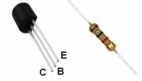
The 2N3906 transistor has three leads. If you place the transistor flat side down with the leads to the bottom, the leads from left to right are the collector, base and emitter.
Strip a small length of insulation off a piece of yellow 20 or 22 gauge wire. Cut the insulation to exactly 3/16 of an inch long. Slip the cut piece over the left lead (collector) and push it flush against the bottom of the transistor.
Strip a small length of insulation off a piece of red 20 or 22 gauge wire. Cut the insulation to exactly 3/16 of an inch long. Slip the cut piece over the right lead (emitter) and push it flush against the bottom of the transistor.
These leggings will set the transistor at the right height above the perf board for soldering and ensure they do not touch the center lead (base) when it is bent to fit. Bend the center leg (base) out 45 degrees from the flat side of the transistor.
With the round side of the transistor facing the terminal block, trial fit the two outside leads (collector and emitter) in column 11 on the component side of the board. The yellow lead (collector) should be in trace 2 and the red (emitter) in trace 1. Bend the bottom of the center lead (base) until it fits in column 9 of trace 1 to the left of the transistor as shown in the following diagram. Fasten the bottom of the leggings to the perf board with a bit of super glue to hold the transistor in place.
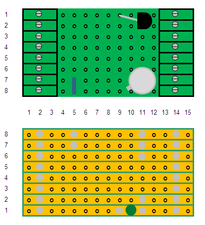
Flip the perf board over. Solder the three leads of the transistor to the board, and trim them. Cut trace 1 between the emitter and base leads as indicated with the big green dot. I used a 1/8 inch drill bit in a pin vise to open the trace.
Bend the leads of a 1K ohm resistor so they will fit in the holes of columns 4 and 8 on the component side of the perf board. Insert it in trace 1 of the board as shown.
Flip the perf board over. Solder the leads to the board, and trim them. Cut trace 1 between the leads as indicated with the big green dot.
Clean the perf board with flux remover. A small hobby awl run between the traces will remove any excess solder.
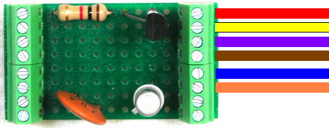
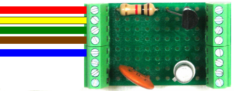
The board should look the same as this, except the capacitor will be smaller and sit across the bottom two traces in column 5.
Fasten the interface board to the rear of the frame with hot glue. The edge of the board should be snug against the two posts in the center of the frame. The chuff activation circuit with the capacitor should be towards the center of the frame, and the sound volume control circuit with the resistor towards the edge of the frame.
That completes the assembly of the interface board. It will be wired after the P8 sound board is installed.
PHOENIX SOUND P8
The Phoenix Sound P8 will be fastened on styrene strips beside the interface board. The strips will allow air to cool the bottom of the sound board.
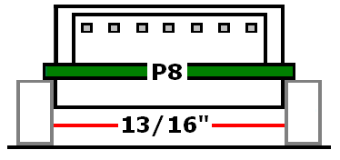
From a 1/8 x 1/4 inch styrene strip, cut two pieces 2 1/2 inches long. Cut two more pieces exactly 13/16 of an inch long. Use CA (super glue) to fasten one of the long pieces on edge to the frame. It should butt up against edge of the interface board.
Using the small pieces as spacers, fasten the other long piece on edge to the frame exactly 13/16 of an inch from the first. When the glue has dried, remove the spacers.
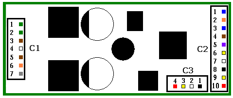
The C1 connector for the P8 has 6 wires: two green, two brown, an orange and a gray. Plug the connector into the header C1 on the end of the P8 board.
Place the sound board on top of the two styrene strips mounted on the frame, with connector C:1 facing the PnP socket. The components on the bottom of the sound board should sit in between the strips, while the P8 circuit board should sit on top of the inside edges. Fasten the corners of the sound board to the strips with small dabs of hot glue.
P8 CONNECTOR C1
Cut the two green wires in P8 connector C1 to five inches in length. Strip a bit of insulation off the wires, and tin them. Solder them to the pads on the side of the K27 PnP socket labeled J1:12 and J1:1. They are right beside the screw terminals for the battery pack wires. This will provide power to the sound board.
OPTIONAL: As shown, a two-position screw terminal block can be soldered to the K27 PnP socket to make fastening the wires easier. These two-position terminal blocks are made by Phoenix Contact and are available from the Mouser Electronics under the manufacturer’s part number 1727010. This screw terminal block, like the battery wire screw terminal block beside them, has an unusual 3.8mm spacing between the pins.
Cut the two brown wires in P8 connector C1 to 4 inches in length. Strip a bit of insulation off the wires, and tin them. Unsolder the connector wires from the speaker and set it aside. Solder the brown wires in P8 connector C1 to the terminals on the speaker.
Cut the orange and gray wires in P8 connector C1 to seven inches in length. Strip a bit of insulation off the wires and tin them. Solder them to the solder pads on the side of the K27 PnP socket labeled “+ MOTOR –“. They are right at the end of the circuit board. Solder the orange wire to the plus pad, and the gray wire to the minus pad. These wires will measure motor speed/voltage which is required for a number of sound functions including chuff averaging.
OPTIONAL: A two-position screw terminal block can be soldered to these pads as well. Like the battery and P8 power terminal blocks, it must have 3.8mm spacing between the pins. The screw terminal block that came with the PnP socket for the battery wires was not as sturdy as the Phoenix Contact ones, so it was replaced as well.
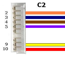
P8 CONNECTOR C2
- The C2 connector for the P8 has nine wires, but only six of them can be used. In this installation they were:
- the orange wire C2:2 for the chuff,
- the blue wire C2:3 for the whistle,
- the brown wire C2:4 for the bell,
- the purple wire C2:5 for blow down,
- the yellow wire C2:9 for sound volume down, and
- the red wire C2:10 for sound volume up.
If preferred the yellow wire C2:6 could be used for chatter instead of the purple wire C2:5 for blow down.
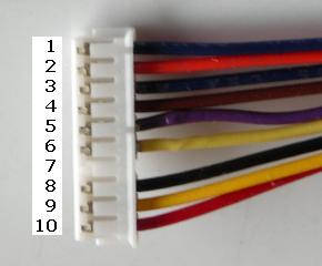
To remove the three unnecessary wires, place the connector in a small workbench vise with the plastic tabs facing up. Slip the blunt tip of an X-Acto knife blade under the side of tab number 1. Lift the tab slightly, and draw the wire out. Repeat the process to remove the other two redundant wires. Patience is required or the connector could be damaged.
Save the black wire from connector position C2:8, it will be used later to wire the chuff activation circuit.
Cut the six remaining wires to two inches in length.
Save the remainder of the orange wire. It also will be used later to wire the chuff activation circuit
Strip a bit of insulation off the ends of the six wires, and tin them. Plug the connector into the 10-pin header C2 on the P8 board.
- Fasten the six wires in the screw terminals on the right side of the interface board in following order:
- the red wire C2:10 for sound volume up in terminal 1,
- the yellow wire C2:9 for sound volume down in terminal 2,
- the yellow wire C2:6 for chatter or the purple wire C2:5 for blow down in terminal 3,
- the brown wire C2:4 for the bell in terminal 4,
- the blue wire C2:3 for the whistle in terminal 5, and
- the orange wire C2:2 for the chuff in terminal 6.
REVOLUTION RECEIVER TRIGGER WIRES
The Revolution receiver has an Auxiliary Control Harness connector with six trigger wires, and a ground wire. The trigger wires are activated by the six function keys numbered 1 to 6 on the Revolution throttle
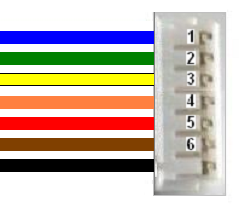
- Doug of this K27 wanted to use the following Revolution throttles keys for specific sound functions:
- key/wire 1 for the whistle,
- key/wire 2 for the bell,
- key/wire 3 for blow down,
- key/wire 5 for sound volume down, and
- key/wire 6 for sound volume up.
Unfortunately only the whistle wire was a colour match for the corresponding P8 sound wire. But like the P8 sound wires they can be removed and changed to match.
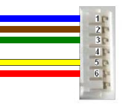
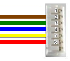
Remove all the trigger wires, except the blue wire 1. Insert the four colours of wires as shown. As there was no match for the P8 purple wire or green receiver wire, they were paired together.
After the wires have been moved, the connector should look like this.
Cut all five wires to six inches in length. Strip a bit of insulation off the ends of the wires and tin them. Plug the Auxiliary Control Harness connector into the rear of the Revolution receiver.
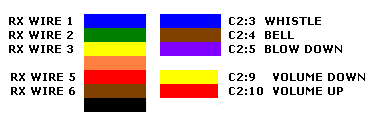
- Fasten the five trigger wires in the screw terminals on the left side of the interface board in the following order:
- the red wire 6 to raise the sound volume in terminal 1,
- the yellow wire 5 to lower the sound volume in terminal 2,
- the green wire 3 for blow down or chatter in terminal 3,
- the brown wire 2 for the bell in screw terminal 4, and
- the blue trigger wire 1 for the whistle in terminal 5.
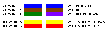
OPTIONAL: As mentioned in previous articles, on my Revolution throttles the trigger keys are used for specific sound functions:
- key 2aBc for the Bell,
- key 4gHi for the Horn/Whistle,
- key 5jkL for Less sound volume, and
- key 6Mno for More sound volume.
If this is a preferred format, the trigger wires in the connector would be arranged as shown. The additional sound function, blow down or chatter, would be triggered by key 3def.
The wires would be fastened to the interface board the same as previously illustrated and described, as they have to align with the P8 sound function wires which have not changed.
That completes the installation of the Revolution trigger wires.
CHUFF ACTIVATION CIRCUIT WIRES
The orange wire C2:2 from the P8 for the chuff sound function was cut and installed in a previous section.
Trim the orange and black wires saved from the P8 C2 connector installation to eight inches in length. Strip a bit of insulation off both ends of the wires and tin them.
Fasten the orange wire in screw terminal 7 on the left side of the interface board, and the black wire in terminal 8.
Solder the orange wire to pad labeled J1:5 on the side of the K27 PnP circuit board. Solder the black wire to pad labeled J1:7. The orange wire connects the optical chuff sensors in the cylinders to the chuff activation circuit. The black wire is a ground.
OPTIONAL: Instead of soldering the wires to the pads J1:5 and J1:7, a three-position screw terminal block can be soldered to them instead. Unlike the battery and P8 power terminal blocks, it has the more common 2.5mm (0.10 inch) perf board spacing between the pins.
OPTION 2: This particular locomotive did not have a rear light on the tender, and Doug preferred to have the headlight on in both directions. To accomplish this, the grounds for both the front headlight (solder pad J1:4) and the rear headlight (solder pas J1:9) must have a jumper soldered across them. In this installation terminal blocks were soldered across all the six pads from J1:4 to J1:9 to fasten the orange and black wires for the chuff activation circuit, and the jumper wire for the headlight grounds.
The terminal blocks are available from the Mouser Electronics under the manufacturer’s part number 1725669 for the three-position or 1725698 for the six-position.
That completes the wiring of the interface board.
P8 PROGRAMMING JACK
Remove the coal doors and coal load from the tender body. Place the tender body on a soft surface beside the frame. Plug the white connector for the P8 programming jack into the 4-pin header (C3) on the edge of the P8 sound board.
ASSEMBLING THE TENDER
On the side of the K27 PnP circuit board is a set of screw terminals labeled + BATT -. They are right above the linking button on the receiver. Fasten the red wire from the battery switch under the positive screw terminal, and the black wire under the negative terminal.
Make sure the battery switch is in the center-off position. Plug the connector on the battery pack into the connector on the battery switch.
Remove the three screws from the frame. Use them to fasten the tender body to the frame, taking care not pinch of the wiring.
Slide the coal doors panel into the front of the tender body.
TESTING THE P8 SOUND BOARD
Place the locomotive and tender on a section of track or test stand, and connect them together.
Turn the Revolution throttle on and check to ensure the K27 information is displayed. Use the ASSIGN FUNCTIONS menu to set the bell trigger to latched.
Be prepared to use function key 5 to turn the sound volume down. Toggle the battery switch to the power position. IT’S LOUD EH?
Place the coal load back on the tender, as it improves the sound quality. Use the throttle to test the different sound functions: whistle, bell, blow down or chatter, sound volume up and down.
CONGRATULATIONS! You have successfully installed a Phoenix Sound P8 in your Bachmann K27.
5 comments
Skip to comment form
Hi Paul
I have read your article for battery and sound. I am confident that I can do this. The only problem is what is the part number for the 1K resistor. Thanks
I have read your article twice and it would be a great aid if you would draw an actual electrical schematic of your chuff circuit and volume circuit. I simply cannot make heads or tails of the written description. However I read schematics quite well. Thank you, John Acton
Author
I do not have a picture of the circuit schematic.
But here is the link to the K27 information on the Phoenix Sound website.
http://www.phoenixsound.com/pdf/BachK27.pdf
Has anyone sucessfully put a Phoenix, revolution and battery into a c-19. And have not needed to use a battery car and have the chuff work properly ?
Author
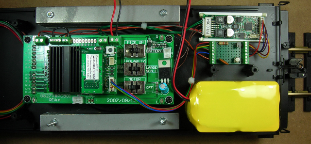
I have not had a Bachmann C-19 in my work shop yet. I know they have a Plug and Play socket for the Revolution receiver in the tender. Looking at the LSOL and Bachmann videos on YouTube, it appears the tender is pretty full with a speaker and electronics. But the K-27 looks the same way when the coal load is removed, and as this article shows a Revolution receiver, large battery and Phoenix Sound P8 were all installed.
This article also shows how to assemble a simple circuit board to get the Chuff to work properly. The board also includes two components to allow the 5th and 6th key on the Revolution throttle to lower and raise the P8 sound volume. Screw terminals at both ends make it easy to connect the Revolution and P8 trigger wires.
You might also post this question on Large Scale Central. I am sure Stan Ames and others would be able to provide information on how to add radio control, battery power, and sound in a C-19. I have operated a C-19 on Stan’s railway and they run beautifully.