
UPDATED DECEMBER 2019 The wiring instructions for the battery switch have been corrected.
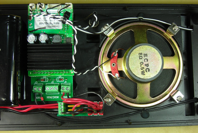
Initially connecting the Revolution receiver with Steam Sounds to the Bachmann sound connector produced erratic chuff sounds at slow speed. Instead the wiring was disconnected and Revolution receiver allowed to generate the chuff rhythm by motor voltage. This provided a clean chuff sound and simplified the installation.
This article illustrates a method of installing radio control, battery power and sound in a Bachmann, Anniversary Edition 4-6-0 locomotive.
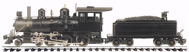
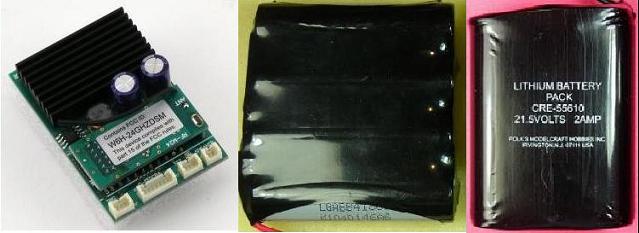
This installation uses an Aristo-Craft Revolution receiver with steam sounds and either a 14.8 volt or 22.2 volt lithium-ion battery.
The article appears long because it is detailed and includes lots of pictures. But if you take your time and follow it step-by-step it is not difficult, and the results are well worthwhile.
Please read this article carefully, highlighting the components that are needed. Sources of supply are suggested for items not sold by your hobby suppliers. OVGRS members can purchase the required components by contacting Paul Norton.
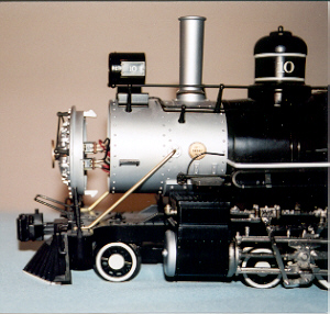
THE LOCOMOTIVE
It is imperative that the track power wiring be disconnected so the locomotive can never pick up track power or feed battery power into the tracks. The result could be electronically catastrophic.
There is no need to open the locomotive to isolate the track power wiring. Open the circular cover on the front of the smoke box hiding the Large Scale/NMRA switch. All the track power wiring is routed through this switch.
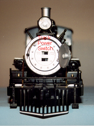
The smoke box cover is held on with tabs on the top and bottom. Carefully pry it off to expose the switch wiring.
The track power wiring is attached to both ends of the Large Scale/NMRA switch.
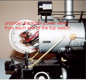
Unsolder these wires from each end of the top switch and cover each of them with shrink wrap.
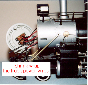
Push the smoke box cover back on and close the circular switch cover. That completes the modifications to the locomotive. Place it back in its packaging for now and set it aside.
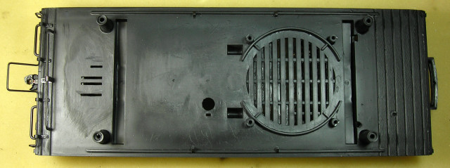
THE TENDER
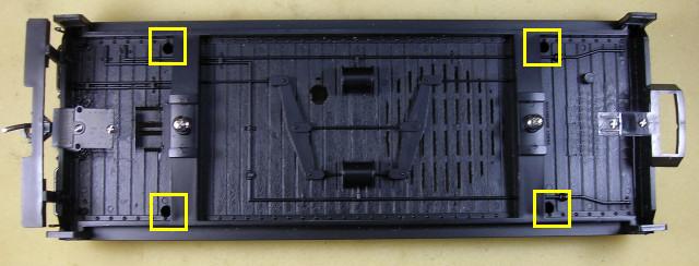
Turn the tender over and remove the trucks. Place the two screws back in the frame so they do not get lost. Set the trucks aside for now. Remove the four screws holding the tender body to the frame.
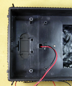
Turn the tender over and carefully lift the tender body from the frame. There are two wires that run from the connector marked LIGHT back to the rear light. Cut these wires just below the shrink wrapped soldered joints.
Fasten the four screws back in the tender body, and set it aside for now.
THE TENDER FRAME
Twist the brake wheel shaft out of the frame so it does not get damaged or bent, and set it aside for now with the tender body.
When this installation is complete, all the electrical components and wiring, except the two wires for the rear light, will be attached to the frame. The tender body can be easily be removed by undoing its four screws and disconnecting the rear light wires from the receiver adapter board screw terminals. This allows the receiver and battery to be accessed for testing or replacement.
Undo the knot in the wires for the connector marked LIGHT and straighten them. Pull the wires out of the two holes in the front of the frame, and set the connector aside for now.
THE BACHMANN SOUND BOARD
In order to install the receiver, battery and battery switch, the Bachmann sound board will have to be removed.
Unsolder the red wire for the connector labeled SOUND from the small circuit board.
Unsolder the gray wire and red wire from the speaker.
Turn the frame over and pull the knob of the shaft on the sound volume switch. Pliers may be required. Remove the nut and washer.
Turn the frame back over. Undo the two small screws holding the sound board to its two posts.
Unsolder the black wire for the connector labeled SOUND from the top of sound volume switch. Undo the knot in the wires and straighten them. Pull the wires out of the two holes in the front of the frame, and set the connector aside for now.
Remove the switch from its hole in the frame. Fasten the washer and nut back on the switch.
Pull the chrome contacts for the sound board battery backwards out of their brackets on the rear of the frame floor.
Place the sound board components including the Sound connector and screws in a small Ziploc bag and tape it a pocket of the locomotives Styrofoam packaging.
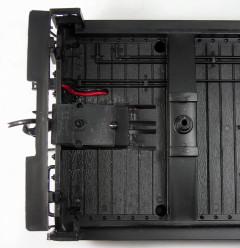
THE TENDER FRAME FLOOR
Remove the four screws and brackets that hold the speaker to the frame. Place the speaker, its brackets and screws in a small Ziploc bag. Set it aside with the tender body for now.
In order to provide a flat surface to mount the battery and receiver, the sound board posts and brackets for its chrome battery contacts on rear the frame floor will have to be removed.
After removing them, sand the area smooth and clean the frame.
THE BATTERY CHARGING CONNECTOR
The female half of an All Electronics 2-wire connector set, shown on the left, will be used as a charging connector for the on-board battery. The connector set is available from All Electronics under catalog number CON-240.
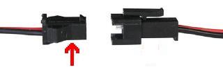
CAUTION: The wires on the connector sets sold by All Electronics may not be positioned the same as the wires on the connectors of lithium-ion batteries and chargers.
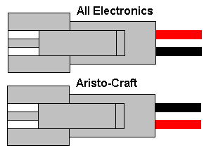
If not, click on the following link to see how to switch the positions of the AE Connector Set Wiring so that proper polarity is maintained.
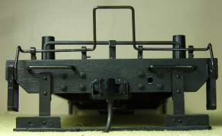
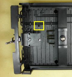
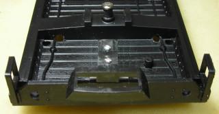
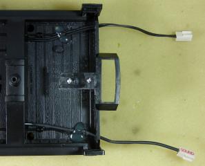
The battery charging connector will be mounted on the rear sill of the frame. On the right side of the sill are a square of nut and bolt details. Drill a hole with a 1/8th inch bit through the sill in the center of the nut and bolt details.
Turn the frame over. Drill another hole through the fourth board from the end of the frame behind the first hole. The new hole should be about an inch from the outside of the sill and right beside the piping detail on the bottom of the frame.
To make it less conspicuous, trim the wings off the charging connector and sand the sides smooth.
With the locking tab on the connector facing up, push the wires through the hole in the sill. Spread a little super glue on the back of the connector and pull the wires until the connector is snug against the sill.
When the glue has dried, push the wires flat against the back of the sill and the bottom of the frame. Add a blob of hot glue over the wires at the back of the sill to provide stress relief and hold the charger snug against the sill.
When the hot glue has hardened, pass the wires through the hole in the frame floor boards and pull them snug.
That completes the installation of the battery charging connector. It will be connected when the battery switch is installed.
THE LINKING BUTTON
The linking button and battery switch will be installed in the middle of the frame just inside the frame girders.
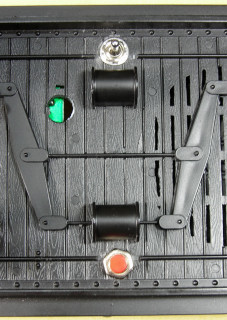
In order to provide a flat surface for the washers and nuts, the piping details on the bottom of the frame in those areas will have to be removed.
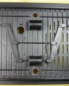
A 1/2 inch Forstner drill bit in a drill press provided the best results. The tip of the bit was placed against the outside edge of the T-junction of the piping and turned until the there was a 1/2 inch circle flush with the frame floor. A small chisel or X-Acto knife with a chisel blade might also be used to remove the piping.
Using the small hole at the top edge of the frame created with the Forstner bit as a starting point; enlarge the hole with a 1/4 inch bit for the battery switch.
Using the small hole at the bottom edge of the frame created with the Forstner bit as a starting point; enlarge the hole with a 9/32nds inch bit for the linking button.
Do not install the linking button at this time. It will be installed when the receiver is installed.
THE LIGHT CONNECTOR
As the rear light will be connected to and powered by the receiver, the connector labeled LIGHT is no longer needed for that purpose. It will be used to power the locomotive, front light and smoke unit instead.
Do not install the connector at this time. It will be added once the receiver is installed.
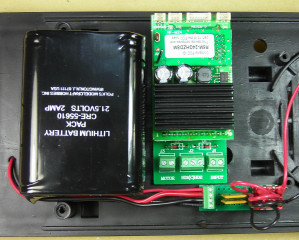
THE LITHIUM-ION BATTERY
As mentioned at the start of his article, there are a number of types of lithium-ion batteries that can be used in this installation.
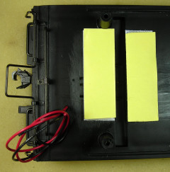
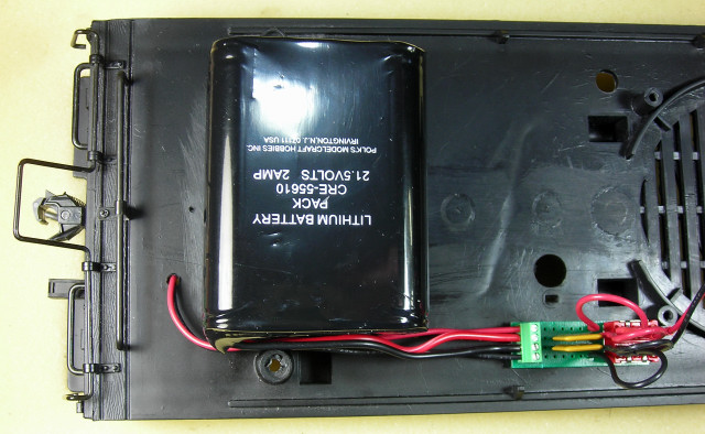
If a 22.2 volt battery is used, cut two strips of Velcro 2 1/2 inches long and fasten them to the to the top of the floor on both sides of the rear truck bolster.
Fasten the battery to the Velcro between the two posts at the rear of the frame floor with the wires tucked in behind the bottom post as shown.
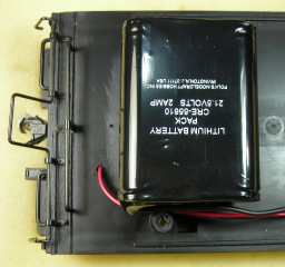
Thread the charging connector wires behind the post and under the battery wires.
That completes the installation of this battery. It will be connected when the battery switch is installed.
If a 14.8 volt, flat battery is used, place the battery between the posts just ahead of the charging connector wires. About 5/16ths of an inch in front of the rear truck bolster, place a mark on both sides of the battery to let a cable tie pass through a hole in the floor. Remove the battery and drill the two holes in the floor with a bit large enough to let the cable tie pass.
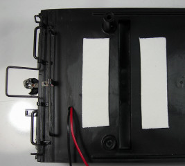
Cut two lengths of double-sided tape 2 1/2 inches long. Apply the strips between the frame posts about 1/4 of an inch to either side of the rear truck bolster.
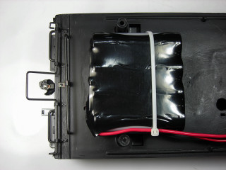
With the top of the battery just in front of the battery charging connector wires, fasten the battery to double-sided tape between the posts.
Pass a cable tie through the holes and around the battery, as well as, the battery and the charging connector wires as shown. The tie should be snug, but not tight enough to damage the pack. That completes the installation of the battery. It will be connected when the battery switch is installed.
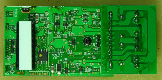
THE BATTERY SWITCH AND FUSES
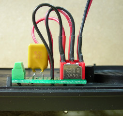
Modern Aristo-Craft locomotives have self-resetting fuses to protect their electronics. In order to add them to this locomotive, a small and simple circuit board will be built to hold them, the battery switch, and screw terminals for the battery and charging connector wires.
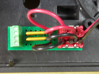
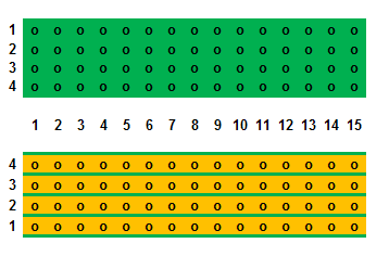
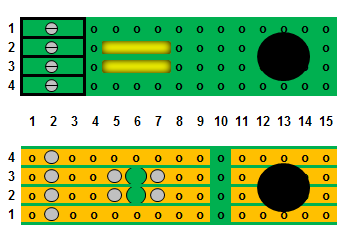
Score and snap a small piece of straight trace perf board four traces wide by fifteen columns long. The straight trace perf board is available from All Electronics under catalog number ECS-4.
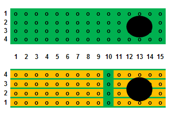
In column 13 between traces 2 and 3, drill a hole for the battery switch with a 1/4 inch bit. On the solder side of the board, cut open all 4 traces across column 10 with a razor saw, and clean it up with a small hobby file. The will isolate the metal parts on the switch from the rest of the circuit board.
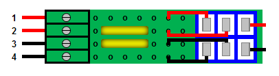
Fasten a 4-position screw terminal block to the component side of the perf board with super glue. The pins of the block should be in column 2 and the openings for the wires should face out.
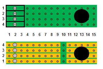
Flip the perf board over and solder the pins of the terminal block to the board. A good soldering iron of at least 40 watts and thin solder wire will be required. The pins and traces must be properly fluxed and heated, before the solder is added and allowed to flow.
The terminal block is manufactured by Phoenix Contact and is available from Mouser Electronics under the manufacturer’s part number 1725672 for the 4-position version.
Flip the board back over and install the leads of a 2.5 amp self-resetting fuse in columns 5 and 7 of trace 2. Flip the board over. Solder the leads to the board, and trim off any excess leads. Using a 1/8 inch drill bit in a pin vise, break open trace 2 between the leads of the self-resetting fuse as indicated with the big green dot in column 6.
Flip the board back and install the leads of a 2.5 amp self-resetting fuse in columns 5 and 7 of trace 3. Flip the board over. Solder the leads to the board, and trim off any excess leads. Using a 1/8 inch drill bit in a pin vise, break open trace 3 between the leads of the self-resetting fuse as indicated with the big green dot in column 6.
The self-resetting fuse are available from Mouser Electronics under the manufacturer’s part number 30R250UU.
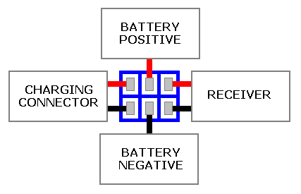
A double-pole, double throw center-off switch will be required to toggle the battery between its charging connector and the receiver.
The DPDT center-off switch is available from Mouser Electronics under the manufacturer’s part number 506-A203SYZQ04.
Cut three 6 inch lengths of 22 gauge red wire and a three 6 inch lengths of 22 gauge black wire. Trim 1/8 of an inch of insulation off one end of all the wires.
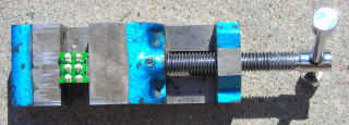
As it is easier to solder and shrink wrap the wires to the terminals of the switch before it is installed; place the switch in a small bench vise with the terminals facing up.
Solder and shrink wrap the three black wires to the right terminals of the switch, and the red to the terminals to the left.
Remove nuts and the washers from the switch. Slide toggle through the hole in the circuit board and use one of the nuts to fasten it in place. The red wires should be in line with trace 1 and the black with trace 4.
Strip 1/4 of insulation off the free ends of the 6 wires attached to the switch.
Place the end of the red wire for the battery (top center terminal on the switch) in column 9 of trace 2, the end of the black wire for the battery (bottom center terminal on the switch) in column 9 of trace 3. Flip the board over and solder the wires to the board.
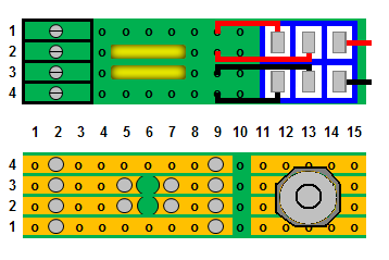
Place the end of the red wire for the charging connector (top left terminal on the switch) in column 9 of trace 1, the end of the black wire for the charging connector (bottom left terminal on the switch) in column 9 of trace 4. Flip the board over and solder the wires to the board.
Clean the solder side of the board with flux remover and an old toothbrush.
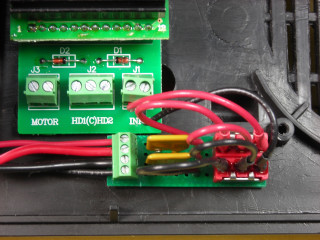
Place the switch toggle of the through the hole on the side of the frame. The screw terminal block on the self-resetting fuse circuit board should face the battery. Use the lock washer and second nut to secure it in place.
CAUTION: Do not let the battery wires touch each other, or anything metal at the same time. Ensure the battery switch is in the center-off position.
Trim the black wire on the battery to a length that will easily reach inside screw terminal 3 on the circuit board. Strip 1/4 inch of insulation of the end of the wire and fasten it under screw terminal 3.
Trim the red wire on the battery to a length that will easily inside screw terminal 2 on the circuit board. Strip 1/4 inch of insulation of the end of the wire and fasten it under screw terminal 2.
Trim the black wire on the charging connector to a length that will easily reach inside screw terminal 4 on the circuit board. Strip 1/4 inch of insulation of the end of the wire and fasten it under screw terminal 4.
Trim the red wire on the charging connector to a length that will easily reach inside screw terminal 1 on the circuit board. Strip 1/4 inch of insulation of the end of the wire and fasten it under screw terminal 1.
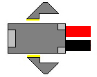
Strip 3/16ths of an inch of insulation off of the ends of the wires of the male half of the All Electronics connector set. Plug the male connector into the battery charging connector on the back of tender. Fasten the leads of a voltage meter across the ends of the male connector wires. Toggle the battery switch forward to test that the polarity of the battery charging connector. If it is correct, toggle the battery switch to its center-off position, and remove the male connector and voltage meter.
If the polarity was not correct, reverse the wires in screw terminals 1 and 4 on the circuit board, and re-test the battery charging connector. Toggle the battery switch to its center-off position, and remove the male connector and voltage meter.
That completes the installation of the battery, battery switch, and charging connector.
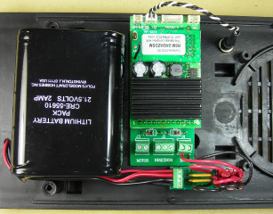
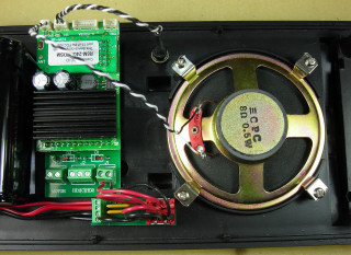
THE REVOLUTION RECEIVER
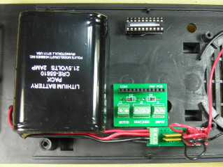
The Revolution receiver will be installed across the frame beside the battery in its adapter board and a 20 position IC socket.
The IC socket is available from Mouser Electronics under the manufacturer’s part number 571-1-390261-6.
Cut two 1 inch long pieces of 1/8 x 3/16ths of an inch styrene. Glue them together in a stack 1/4 inch tall x 3/16ths of an inch wide. Glue the stack between the pins on the bottom of the IC socket.
Push the ten pins on the rear of the receiver into the back set of terminals on the IC socket.
Push the 12 pins on the front of the receiver into the adapter board that came with it.
Place the receiver on the frame beside the battery with the front edge of the adapter board flush against the battery switch circuit board. Using a pencil, draw marks on the frame on both sides of the adapter board and IC socket stack.
Lift the receiver and lay a bead of hot glue between each set of marks. With the front of the adapter flush against the battery circuit board, lower the adapter board and IC socket stack into the beads of hot glue.
While the foam that came with the receiver could be used to support the rear pins of the receiver, it is not as sturdy as the IC socket and would block cooling air from passing under the receiver.
Fasten the remaining red wire on the battery switch (top right terminal) into the inside screw terminal on the adapter board labeled INPUT. Fasten the remaining black wire on the battery switch (bottom right terminal) into the outside screw terminal on the adapter board labeled INPUT.
Remove the locking nut and washer from the linking button. Using just the nut, install the linking button in the hole opposite side of the frame from the battery switch. Plug the small connector into the 3-pin header on the back of the receiver labeled SET.
You may have to remove the receiver in order to plug the connector in as it is a tight fit.
THE SPEAKER
Fasten the speaker back on the frame floor using the four bracket and screws. The speaker terminals should face the receiver.
Plug the speaker connector that came with the Revolution receiver into the 2-pin header on the back of the reliever labeled SPEAKER. You may have to remove the receiver in order to plug the connector in as it is a tight fit.
Cut the wires to a length that will easily reach the speaker terminals. Stripe a bit of insulation of the ends of the wires and solder them to the speaker terminals.
That completes the installation of the speaker.
THE POWER CONNECTOR
Thread the wires for the connector marked LIGHT through the two holes on the bottom edge of the frame. Leave enough slack in the wires for them to easily reach the right-hand two-pin header on the rear of the locomotive.
Turn the frame over and apply hot glue the wires of the connector to hold them in place.
Strip 1/4 inch of insulation off the wires and fasten them under the screw terminals labeled MOTOR. Polarity does not matter, as it will change with each change in direction. This connector will now supply power from the receiver to the locomotive.
Apply a dab of hot glue to the wires of the POWER (LIGHT) connector where they pass around the speaker.
That completes the installation of the POWER connector.
THE SOUND CONNECTOR
UPDATED OCTOBER 2015: The following paragraphs and pictures described how to install the connectors and wires to have the Bachmann locomotive activate the chuff sound. Testing of the two locomotives shown in this article however, revealed that the chuff generated this way was erratic at slow speeds. The wiring and connectors were removed and the Revolution receiver was used to changed the chuff rhythm to match the motor voltage.
If it is important that the chuff sound be in sync with the rotation of the locomotive’s driving wheels, it is suggested that a reed switch and magnets be installed. To get an idea how that might be done, read the article on this web site about installing sound in an Aristo-Craft Pacific.
THE REAR LIGHT
There are two long tabs in the tender body that were used to hold a 9-volt battery in place. These tabs will stop the shell from fitting over either battery. Score the tabs near the top of the tender body with an X-Acto knife and snap them off. Sand off what is left of the tabs with an emery board or a small file.
There is a red and black wire with a resistor attached to the rear light. Remove the shrink wrap from the free end of the red wire and from the free end of the resistor on the black wire.
Cut a 6 inch length both a red wire and black wire. Remove 1/4 inch of insulation off both ends of the wires.
Remove about 1/4 inch of insulation off the free end of the red wire from the rear light. Solder and shrink wrap one end of the 6 inch red wire to the free end of the rear light red wire.
Solder and shrink wrap one end of the 6 inch black wire to the free end of the resistor on the rear light black wire.
Usually the red wire for a LED would be the positive wire and the black the negative. The red wire would be fastened under the screw terminal on the adapter board labeled COM and the black wire under the screw terminals labeled HD1. However the wire colours on the rear lights of most Bachmann large scale locomotives are reversed. Fasten the free end of the black wire under screw terminal on the adapter board labeled COM, and the red wire under the screw terminal labeled HD1.
Remove the 4 screws from the tender body and use them to attach the body to the tender frame.
That completes the installation of all the components required to provide battery power, radio control and sound for this locomotive. All that is left to do is program the receiver and test the locomotive.
PROGRAMMING THE RECEIVER AND THROTTLE
To program the receiver follow the instructions in the Installation and Operation Manual for the Revolution Train Engineer on the CD that came with the set. The Revised Manual and other information is also available on the Aristo-Craft web site as an Adobe pdf file. To read or download the revised manual, click on the link.
Toggling the battery switch towards the rear of the tender will power the receiver, the center position is off, and toggling forward will connect the charging connector.
Once the receiver and throttle have been linked, check to ensure function F1 has been set to LATCH in the AUXILLARY FUNCTION SETUP menu, or the sound board will not work.
TESTING THE LOCOMOTIVE
Place the locomotive on a set of rollers or a length of track. If installed, plug the SOUND connector into the left 2-pin header on the rear of the locomotive. Plug the POWER (LIGHT) connector into the right 2-pin header on the rear of the locomotive.
- Throttle key 1 turns the sound off and on.
- Throttle key 2 rings the bell 8 times.
- Throttle key three sounds the whistle 3 times.
- Throttle key 7 sets the sound volume high.
- Throttle key 8 sets the volume medium.
- Throttle key 9 sets the volume low.
In my train work shop, I found all the volume settings were loud. This might not be a problem outdoors, however the speaker is only rated for 1/2 a watt. I have got into the habit of turning the sound off when shutting a locomotive down. When the locomotive is turned back on, throttle key 9 is pushed for the lowest volume, and then throttle key 1 is pushed to turn the sound on.
The bell is a great sounding hand rung bell, and the deep and lonesome whistle is something even the late Johnnie Cash would appreciate.
ENJOY your battery powered and radio controlled Bachmann Annie with steam sounds!
2 comments
Thank you Roger for bringing the incorrect wiring instructions for the battery switch to my attention. I have corrected the instructions and have indicated on the title page these instructions have been updated.
I considered buying one of the new chassis when Bachmann had them on sale, and updating an old Big Hauler locomotive. However after reading some on-line instructions that indicate it is not just a slip-in change, I decided not to as I already have too many projects to work on. Search and see if this is something that you would feel comfortable doing.
Yes the new chassis do have metal side rods and updated gear boxes.
I am a new to G scale and purchased my first Big Hauler locomotive. While it is not the Annie version your article is very informative and I’m sure with slight modifications will be very useful for the conversion of my loco. I read this in great detail trying to absorb each step.
A question, where you describe the building of the battery switch & fuse circuit board the following text does not seem to match up with your diagrams & photos. “Place the end of the red wire for the battery (top center terminal on the switch) in column 9 of trace 1, the end of the black wire for the battery (bottom center terminal on the switch) in column 9 of trace 4.” The photos & diagrams appear to show them being connected to trace 2 & 3 respectively with the wires for the charging connector going to traces 1 & 4. Am I missing something here, quite possible, or is this a typo?
As my loco is not an Annie, I do not have the switch at the front of the smoke box for a simple disconnect of all of the track power pickups & I only have a single plug at the back of the loco for the chuff sound. Therefore I assume a more complete tear down of my locomotive will be required to make the modifications.
Another question, Backmann currently has the Annie replacement chassis available for only $45, would I be further ahead to purchase one of those to make this conversion? I believe that would also get me the metal side rods & valve gear?
Thank you for the effort you have put into this great & very informative article! Roger