
This article details the conversion of an Aristo-Craft FA-1 from track power to on-board, radio control and battery power. The Plug and Play features are used to install an Aristo-Craft lithium-ion battery pack and 2.4 GHz Revolution receiver.
Test the locomotive and both of its MU connectors to ensure everything is functioning properly before starting this project. Raise the motor blocks so the wheels are free to turn. Plug the battery into the front MU connector. The motors should respond in either track power mode (motor switch on) or battery power mode (motor switch off). Unplug the battery.
If the motors did not respond, click on the following link FA-1 MU Connector Fix before proceeding with another connector test.
Read the article slowly and completely, making note of the components that are required.
Nothing in this conversion prevents the locomotive from being returned to its original condition for re-sale at a later date.
THE SHELL
Place the locomotive upside down on a soft engine cradle taking care not to damage the horns.
Remove the six screws outlined in red from the base of the fuel tank, and set it aside for now. Fasten the screws back in the frame so they do not get lost or mixed up with others.
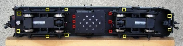
Remove the ten screws outlined in yellow that hold the shell to the frame.
- Two are at the very front under the pilot.
- Two are under the rear of the front truck.
- Four are under front of the rear truck.
- Two are at the very rear of the frame.
Remove the small screws holding the mud flaps to the rear of the shell.
Lift the frame from the shell from the front to the back. If it sticks, check to see if the ends of any grab irons or railings have been pushed inside the shell. Set the frame right side up beside the shell.
Fasten the rear mud flaps back on the shell.
Fasten the ten screws back in the shell so they do get lost or mixed up with others.
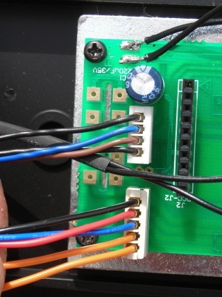
Unplug the white plastic, four and five-wire connectors from the rear of the Plug and Play printed circuit board marked PCB-01.
Remove the two screws holding the plastic diesel engine to the frame, and set it aside for now. Fasten the two screws back in the frame so they do get lost or mixed up with others.
Unplug the speaker from the printed circuit board PCB-02.
Set the shell aside for now.
TRACK POWER WIRES
It is imperative that the track power wiring be disconnected so the locomotive cannot pick up track power or feed battery power into the tracks. The result could be electronically catastrophic.
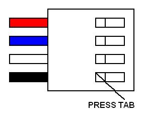
Unplug the two, white plastic, 4-wire connectors at each end of the front printed circuit board marked PCB-02.
Remove the black and white track power wires from both by pressing down on the small metal tabs in the connectors, and gently pulling on the wires.
If the small red connectors for the track power wiring are inside the frame, unplug them. Place the black and white wires that were removed from the white plastic, 4-wire connectors in a Ziploc bag labeled with the engine model name, road name, and road number.
If the connectors are not inside the frame, the Plug and Play circuit board and the motor blocks will have to be removed to unplug them.
Remove the three nuts holding the Plug and Play board to the frame.
Turn the frame over. Two screws inside the side frames hold the motor blocks to their cradles. Remove the screws and lower the motor blocks until the connectors with the black and white wires can be unplugged. Place the black and white wires that were removed from the white plastic, 4-wire connectors in a Ziploc bag marked with the engine model name, road name, and road number.
Push the remaining connectors through the holes in the frame to hide any excess wiring. Re-install the motor blocks and the Plug and Play printed circuit board.
THE LITHIUM-ION BATTERY PACK
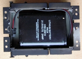
As the fuel tank will carry the lithium-ion battery pack, remove the weight and place it in a separate Ziploc bag so it does not damage the other parts. Label the bag with FA-1, as well as, the road name and number.
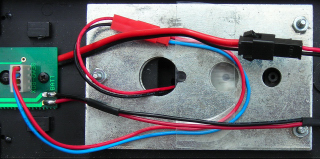
Place a Velcro dot or strip on the bottom of the fuel tank and the battery. Install the battery as shown.
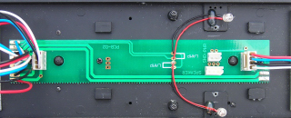
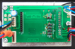
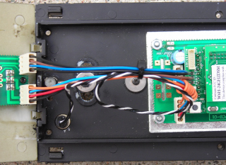
Remove the three screws that hold the long printed circuit board (PCB-02) to the top of the frame. Lift the circuit board.
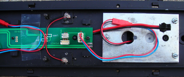
Turn the frame over. Pass the battery pack connector through the square hole closest to the cab that was covered with PCB-02. Remove the six screws from the frame and fasten the fuel tank back on to it.
Turn the frame over. Fasten PCB-02 back on the frame with the small screws at the back and middle of the board. If you have a longer screw that can be used to fasten the front of the board, use it to snug the board down over the battery pack wires.
Do not over-tighten the screw or you may crack the printed circuit board.
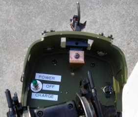
THE BATTERY SWITCH
As the battery pack will be charged on-board, a double-pole double-throw (DPDT) center-off switch is needed to toggle the battery pack between its charging connector and the receiver.
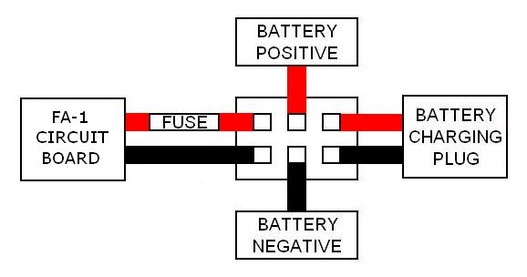
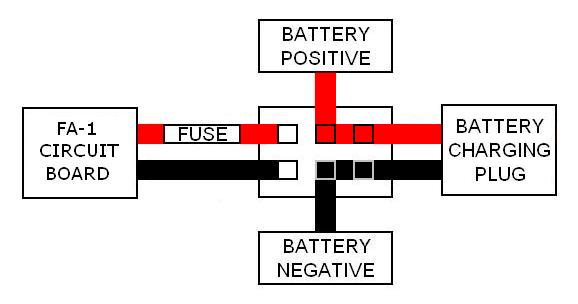
Toggling the switch backward will connect the battery pack through one end of the switch to its charging connector.
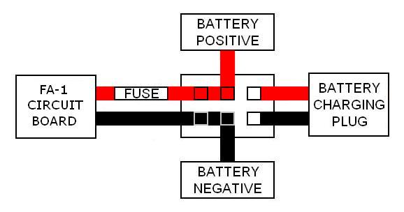
Toggling the switch forward will connect the battery pack through the other end of the switch to power the receiver through the locomotive’s circuit boards.
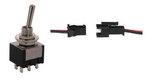
The DPDT center-off switch and 2-wire connector sets used to connect it are both available from All Electronics under catalog numbers MTS-12 and CON-240 respectively. OVGRS members can purchase the DPDT switch and connector sets by contacting Paul Norton.
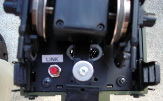
The switch will be installed under the front pilot opposite the bell. This will allow the switch to be accessible, but hidden when running the locomotive.
Un-solder the wires for the redundant front MU connector from the front of printed circuit board PCB-02. Carefully remove the hot glue and gently pull the MU connector wires through the hole in the pilot.
Un-solder the wires for the redundant rear MU connector from the rear of PCB-01, the Plug and Play printed circuit board. Carefully remove the hot glue and gently pull the MU connector wires through the hole in the frame.
Place the MU connectors in the Ziploc bag with the track power connectors.
Remove the two screws that hold the pilot to the frame. Fasten the screws back in the frame so they do not get lost or mixed up with others.
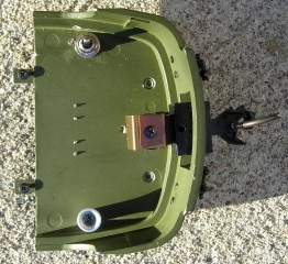
Drill a hole in the pilot opposite the bell with a 1/4 inch bit. Install the DPDT switch so it toggles back and forth.
Set the switch in the center-off position.
THE BATTERY CONNECTOR
The male half of an All Electronics, 2-wire connector set is used to connect the lithium-ion battery pack to the DPDT switch. It has the same connector as an Aristo-Craft lithium-ion battery charger.
The wires on the connector sets sold by All Electronics may not be positioned the same as the wires on the connectors of lithium-ion batteries and chargers. If not, click on the following link to see how to switch the positions of the AE Connector Set Wiring so that proper polarity is maintained.
Cut the wires of the male half of an AE connector set to a length that will easily reach from the switch to the connector on the lithium-ion battery pack. Solder and shrink wrap the wires to the center terminals of the switch as shown in the following diagram.
CAUTION: Do not connect the lithium-ion battery pack at this time.
THE BATTERY CHARGING CONNECTOR
The female male half of the All Electronics, 2-wire connector set is used as the charging connector. It has the same connector as an Aristo-Craft, lithium-ion battery pack.
Remove the bell from the pilot and place in the Ziploc bag with the other parts.
Drill a hole with a 5/16 inch bit in the pilot in place of the bell. Drop the wires of the connector through the hole. Spread the wings of the connector out and wiggle the base through the hole. The base is held with a 1/4 inch spade terminal which is secured with hot glue as shown in the following photo.
Cut the connector wires to a length that will easily reach the front of the switch.
Solder and shrink wrap the wires to the switch as shown in the diagram.
THE RECEIVER
As the receiver will be installed in the Plug and Play socket, it cannot be wired directly to the battery switch. The remaining terminals of the switch will be wired to the solder pads left by the redundant front MU connector.
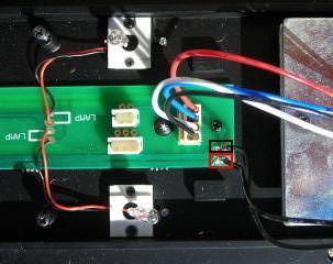
Cut a length of black wire that will easily reach from the solder tab outlined in black on the front of PCB-02 to the switch on the pilot.
Solder one end of the wire to the solder tab. Solder and shrink wrap the other end to the switch as shown in the following diagram.
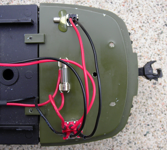
In order to protect the receiver, a fuse will be installed in the red wire. OVGRS members can purchase the fuse and its holding clips by contacting Paul Norton.
Using a scrap of perf board as a guide, mark the four holes required for the pins of the fuse holding clips on the top of the pilot. Drill the four holes with a 3/64 inch bit. Push the clips into the holes and test fit the fuse.

Cut a length of red wire that will reach from the solder tab on the front of PCB-02 to the fuse on the pilot. Solder one end of the wire to the solder tab.
Remove the fuse and holding clips. Solder the other end of the red wire to the base of one of the fuse holding clips.
Cut a length of red wire that will easily reach between the fuse and the switch. Solder one end of the wire to the base of unwired fuse holding clip. Solder and shrink wrap the other end to the last open terminal on the switch.
Push the fuse clips into the holes in the pilot and install the fuse. The pins of the fuse holding clips should protrude from the bottom of the pilot just enough to be tested for continuity with a multimeter.
Remove the DC plug from the front, 12 pin socket of the Plug and Play printed circuit board PCB-01. Plug the receiver in ensuring all the pins line up properly.
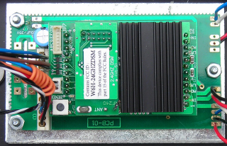
Raise the antenna.
THE LINKING SWITCH
Drill a hole in a rear corner of the frame with a 5/16 inch bit. Install the linking switch as shown.
Plug the linking switch into the back of the receiver on the 2-pin header next to the small gray button.
ACTIVATING THE BATTERY PACK
CAUTION: Check to ensure all the wiring on one side of the DPDT switch is red, and all the wiring on the other side is black. Check that the DPDT switch is in the center-off position. Check to ensure the colour coding of the wires on the lithium-ion battery pack and the connector soldered to the center terminals of the DPDT switch match.
Plug in the battery pack.
CHARGING THE BATTERY PACK
If the battery pack has not been charged, connect an Aristo-Craft, lithium-ion battery pack charger to the connector on the front pilot and toggle the DPDT rearward.
Check the battery pack every hour with a voltage meter. The pack voltage should not exceed 25.2 volts, and should not require more than four hours on the charger.
Return the switch to its center-off position and remove the charger.
PROGRAMMING THE RECEIVER
Place the shell beside the frame.
Plug the white, four and five-wire connectors into the rear of the Plug and Play printed circuit board marked PCB-01.
Plug the speaker back into printed circuit board PCB-02.
Use the two screws in the frame to re-install the plastic diesel engine.
Raise the motor blocks so the wheels are free to turn.
Toggle the battery switch on the pilot forward to power the receiver. The interior lights should come on.
Program the receiver in accordance with the instructions provided in the Installation and Operation Manual for the Revolution Train Engineer. The manual is available on the Aristo-Craft web site as an Adobe pdf file. To read or download the manual, click on the link.
Test to ensure the motors and headlight respond properly. Toggle the switch to the center-off position to take the receiver and battery off-line.
Remove the ten screws from the shell, and fasten it back to the frame.
CONGRATULATIONS! You now have an FA-1 with on board, radio-control and battery power.

ENJOY!