
27 August 2020
Be aware that some of the USA Trains locomotive project articles that I posted years ago are somewhat out of date. The Crest Revolution receivers at that time all had Pulse Width Control for the output power. The voltage spikes in PWC would not let the light bulbs work properly in some USAT diesels. As I result I removed the USAT main circuit board and headlight circuit boards and replaced the headlight and number board lights with LEDs.
Precision RC now makes DC Linear Revolution receivers, so you no longer have to remove the main circuit board and change the lights in USAT diesels. Some of the new USAT diesels also have LED lights that work with the Revolution PWC receivers.
Some of the Super Sockets I built at that time were also rather wide to accommodate all the P8 wiring. Now I make a small separate circuit board for the six Revolution accessory wires and P8 sound wires. This circuit board also has small components that replace the Phoenix Sound volume switch, and allows the volume to be adjusted on the fly using the Revolution throttle.
INTRODUCTION
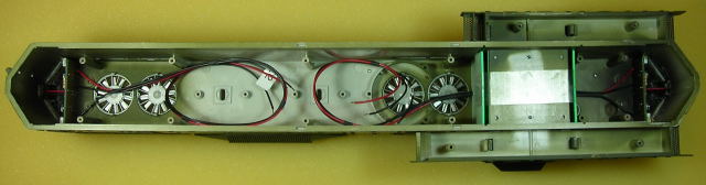
This article details a method used to add a Phoenix Sound P8 to a Battery Powered and Radio Controlled USA Trains GP-9. If the instructions from the previous article were followed, the components and wiring should look like the following pictures.
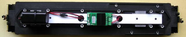
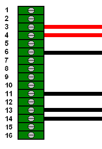
Twelve wires are fastened under the 7 screw terminals on the Plug and Play Board: 2 for the battery switch, 4 for the motors, and 6 for the LED lights. Adding the P8 sound board and Revolution receiver trigger wires however, adds an additional 16 wires for a total of 28. That is far too many wires for just 7 screw terminals, and would result in a confusing spaghetti bowl of wiring. To keep the wires organized, the Plug and Play Board will be replaced with a Super Socket to hold the receiver and interface with the sound board.
The Super Socket is easy to assemble and the terminal blocks on the ends provide an individual screw terminal for each of the wires. Additional components such as a transistor, resistor, and polyfuses are also mounted on the circuit board. The transistor and resistor allow the Revolution throttle to raise and lower the sound volume, making the toggle switch supplied by Phoenix Sound redundant. The polyfuses protect the battery, receiver, sound board, and LED lights.
Please read this article carefully highlighting the components that are needed. Sources of supply and part numbers are suggested for items not sold by hobby suppliers. OVGRS members can purchase all the electronic components required to assemble the Super Socket by contacting Paul Norton.
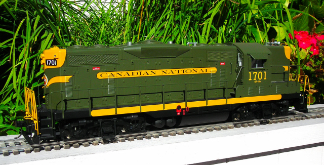
The article is long because it detailed and includes lots of pictures, but if you take your time and follow it step-by-step it is not difficult, and the results are well worthwhile. Although a GP-9 was used for this installation, the instructions could be used as a guide to install a Phoenix Sound P8 in most Aristo-Craft or USA Trains, non Plug and Play, 4-axle diesels.
OPENING THE LOCOMOTIVE
Carefully remove the handrails from the sides and ends of the locomotive. A small, flat screwdriver can be used to gently pry the stanchion tabs from their holes in the frame if necessary. Folding a piece of vinyl tape over the end of the screwdriver may prevent the paint from being scratched.
Place the locomotive upside down in a soft engine cradle taking care not to damage the horns.
There are 14 screws that hold the shell to the frame and some of them are hard to reach. Remove 2 side frames from one side of the locomotive, and place the 6 screws in a small container so they do not get lost.
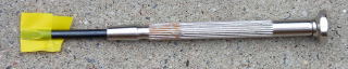
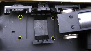
Slip the rear axle of the long hood motor block from its remaining side frame, and flip the motor block towards the center of the locomotive as shown. Remove the four screws outlined in yellow and place them in the small container. Flip the long hood motor block back, and slip the axle back in the side frame. Fasten the other side frame back on.
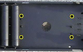
Remove the 4 screws outlined in yellow from the fuel tank area, and place them in the small container with the others.
Slip the front axle of the short hood motor block from its remaining side frame, and flip the motor block towards the center of the locomotive. Remove the 2 screws outlined in yellow and place them in the small container with the others. Flip the front motor block back, and slip the axle back in the side frame. Fasten the other side frame back on.
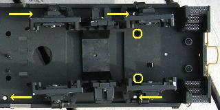
To remove the all 4 screws indicated with the yellow arrows that hold the battery boxes to the frame, the fuel tank will have to be lifted. Remove the two screws that hold the bottom of the fuel tank to the frame.
Remove the battery box screws, and place them in the small container with the others. Fasten the fuel tank back on.
Turn the locomotive over and set is beside the engine cradle. Holding the ends of the shell, carefully lift it straight up. The whole shell (long hood, cab, battery boxes and short hood) will lift off as one piece.
Set the shell on the engine cradle beside the frame. Place a label on each of the black headlight ground wires: HD1 for the rear headlights, and HD2 for the front headlights.
Remove the 12 wires from under the screw terminals on the Plug and Play Board. Fasten the 4 shorter screws back in the battery boxes and the 10 longer screws back in the shell so they do not get lost or mixed up with others. Set the shell aside for now.
Remove the linking button connector from the header on the back of the Revolution receiver. Remove the Revolution receiver from the Plug and Play Board and set it aside for now.
Peel the Plug and Play Board off the components platform and set it aside. Clean the double-sided tape and any residual glue from the platform.
THE SUPER SOCKET
A Super Socket will be assembled to replace the Plug and Play Board.
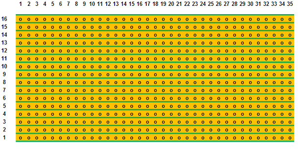
It is made from a perf board available from All Electronics under catalog number ECS-4. Score both sides of the perf board and snap off a piece 16 traces down by 35 columns across. Sand the edges smooth.
Fasten two, 8-position, screw terminal blocks, or any combination of terminal blocks that will cover all 16 traces, to each end of the component (green) side of the perf board with super glue. The pins of the blocks should be in columns 2 and 34, and the openings for the wires should face out.
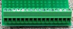
The terminal blocks are manufactured by Phoenix Contact and are available from Mouser Electronics under the manufacturer’s part number 1725711 for the 8-position version.
The Revolution receiver uses only 4 of its 12 front pins to receive power, control the motors, and activate the lights. The 2 two pins on each edge are for power, the third pins in from each edge are for the motors, and fourth pins in are for the front and rear headlight grounds.
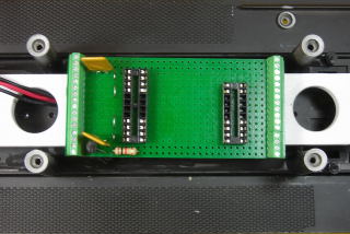
By removing the unused terminals from the center of the IC sockets used to mount the receiver, the center four pins of the receiver can be isolated. Now the screw terminals and their connected traces then can be used to install wires between the P8 sound board and Revolution receiver.

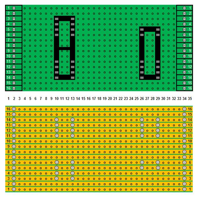
Remove the 8 inside terminals from a 24 pin IC socket and 20 pin IC socket as shown in the diagram above, by pushing up a bit at a time on the pins with needle-nosed pliers. These IC sockets are available from Mouser Electronics under the manufacturer’s part numbers 1-390261-8 and 1-390261-6 respectively.
Fasten the IC sockets to the component side of the perf board with super glue as shown in the following diagram. Their pins are should be in columns 10 and 13, 26 and 29. The pins of the Revolution receiver should line up with the outer row of terminals on each socket.
Flip the perf board over and solder the pins of the IC sockets and terminal blocks to the board. A good soldering iron of at least 40 watts and thin solder wire will be required. The pins and traces must be properly fluxed and heated, before the solder is added and allowed to flow.
SELF-RESETTING FUSES
Modern Aristo-Craft, Plug and Play locomotives have self-resetting polyfuses to protect their electronics. The same polyfuses will be added to provide protection for the battery, receiver, sound board, and LED lights. The polyfuses are available from Mouser Electronics under the manufacturer’s part number 30R250UU.
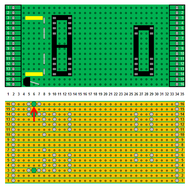
In trace 3 of the component side of the perf board, insert the leads of a polyfuse in the holes of columns 5 and 7. Flip the perf board over, flux and solder it in place, and trim the leads. Break open trace 3 between the leads as indicated with the red arrow, using a 1/8 inch drill bit in a pin vise.
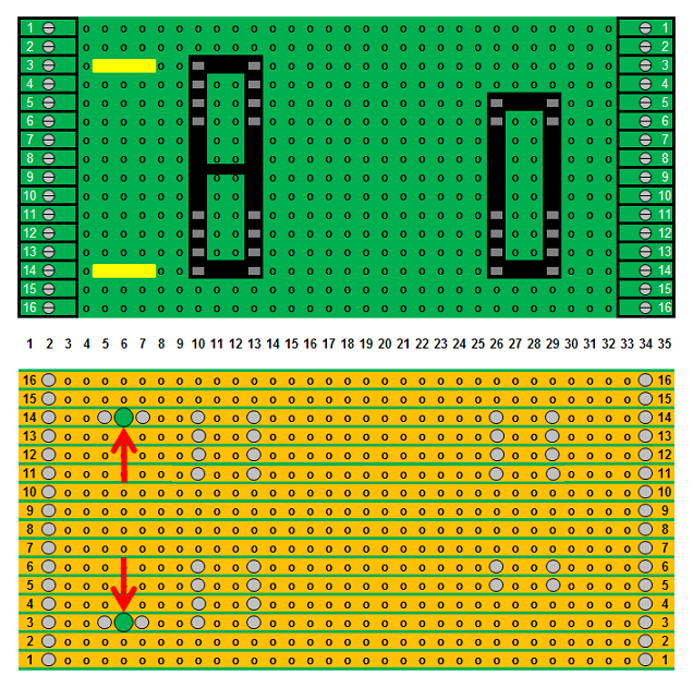
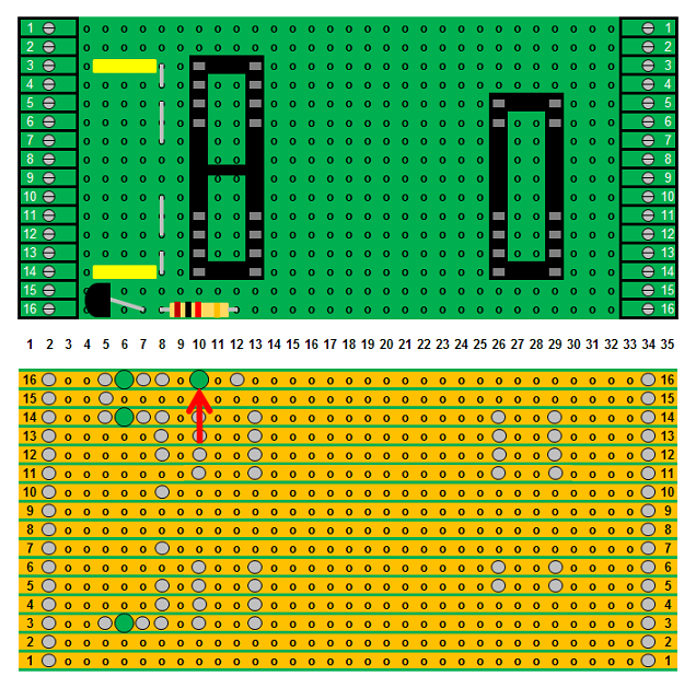
In trace 14 of the component side of the perf board, insert the leads of a polyfuse in the holes of columns 5 and 7. Flip the perf board over, flux and solder it in place, and trim the leads. Break open trace 14 between the leads as indicated with the red arrow, using a 1/8 inch drill bit in a pin vise.
Traces 3 and 14 on the Super Socket will be powered by the lithium-ion battery through wires from the battery switch. But traces 4 and 13 must also be linked to battery switch to provide power to the receiver, P8 sound board, and LED lights. In order to link the two traces, jumpers must be installed.
Strip the insulation off a length of 22 gauge solid core wire. Cut and bend a jumper to fit between the holes of traces 3 and 4 on the component side of the perf board. Insert it in column 8 as shown. Flip the board over, flux and solder it in place, and trim the leads.
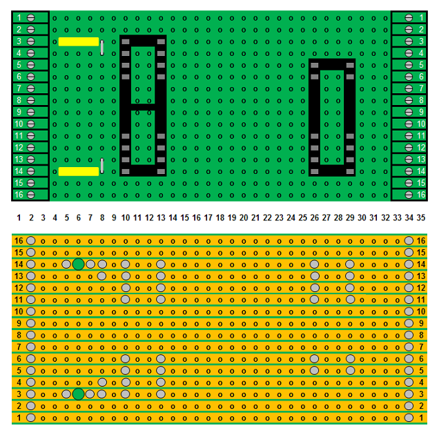
Cut and bend another jumper to fit in the holes of traces 13 and 14 on the component side of the perf board. Insert it in column 8 of as shown. Flip the board over, flux and solder it in place, and trim the leads.
PHOENIX SOUND MOTOR SPEED SENSING CIRCUIT
The Phoenix Sound P8 has a circuit that measures the voltage of the motors and generates the appropriate engine sounds as the diesel changes speed. In order to link the P8 wires and motor wires fastened to the Super Socket, jumpers must be installed.
Strip the insulation off a length of 22 gauge solid core wire. Cut and bend a jumper to fit in the holes of traces 5 and 7 on the component side of the perf board. Insert it in column 8 as shown. Flip the board over, flux and solder it in place, and trim the leads.
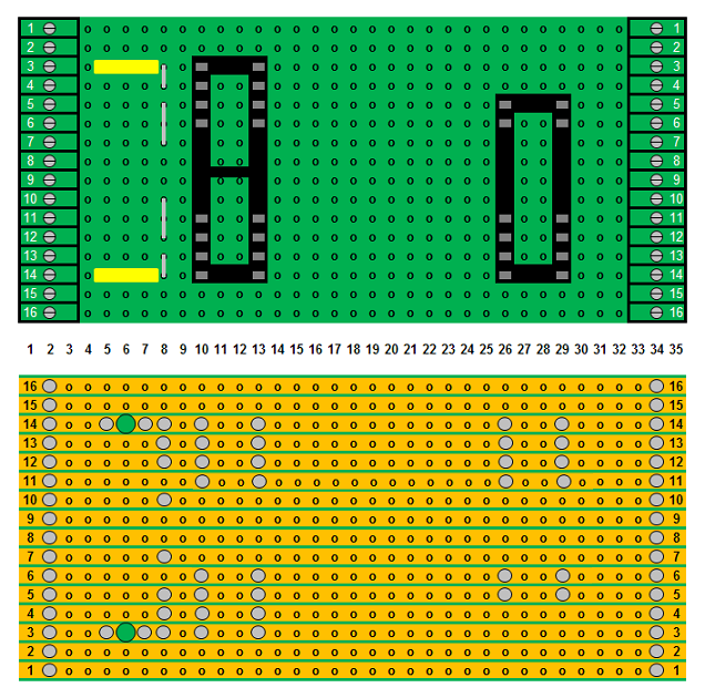
Cut and bend another jumper that to fit in the holes of traces 10 and 12 on the component side of the perf board. Insert it in column 8 of as shown. Flip the board over, flux and solder it in place, and trim the leads.
PHOENIX SOUND VOLUME CONTROL CIRCUIT
Ordinarily the volume on a Phoenix Sound board is raised and lowered using a momentary switch. But hiding the switch so it does not alter the appearance of the locomotive usually means that it cannot be accessed while operating. Fortunately Phoenix Sound has designed a small circuit that allows the volume to be raised and lowered using two keys on the Revolution Train Engineer throttle.
The circuit uses a 1K resistor and a 2N3906 or equivalent transistor which will be soldered in traces 15 and 16 of the Super Socket. The resistor and transistor can be purchased from All Electronics under catalog numbers 293-1K and 2N3906 respectively.
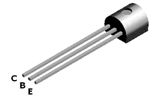
The 2N3906 transistor has three leads. If you place the transistor flat side down with the leads to the bottom, the leads from left to right are the collector, base and emitter. Relax, that’s all you have to know about this device.
Strip a small length of insulation off a piece of yellow (or black), 22 gauge wire. Cut the insulation to exactly 3/16 of an inch long. Slip the cut piece over the left lead (collector) and push it flush against the bottom of the transistor.
Strip a small length of insulation off a piece of red, 22 gauge wire. Cut the insulation to exactly 3/16 of an inch long. Slip the cut piece over the right lead (emitter) and push it flush against the bottom of the transistor.
These leggings will set the transistor at the right height above the perf board for soldering and ensure they do not touch the center lead (base) when it is bent to fit. Bend the center leg (base) out 45 degrees from the flat side of the transistor.
With the round side of the transistor facing the terminal block, trial fit the two outside leads (collector and emitter) in column 5 on the component side of the perf board. The yellow (or black) lead (collector) should be in trace 15 and the red (emitter) in trace 16. Bend the bottom of the center lead (base) until it fits in column 7 of trace 16 to the right of the transistor as shown in the following diagram. Fasten the bottom of the leggings to the perf board with a bit of super glue to hold the transistor in place.
Flip the perf board over, flux and solder the three leads of the transistor to the perf board, and trim them. Break open trace 16 between the emitter and base leads as indicated with the red arrow, using a 1/8 inch drill bit in a pin vise.
Bend the leads of a 1K ohm resistor so they will fit in the holes of columns 8 and 12 on the component side of the perf board. Insert it in trace 16 of the board as shown.
Flip the perf board over, flux and solder it in place, and trim the leads. Break open trace 16 between the leads as indicated with the red arrow, using a 1/8 inch drill bit in a pin vise.
Clean the perf board with flux remover. A small hobby awl run between the traces will remove excess flux and solder.
Place the Super Socket evenly between the two large holes in the components platform with the polyfuses facing the battery. Move the socket back and forth across the platform scoring it slightly with the bottom of the terminal block pins. Lift the socket and place a good run of hot glue across the score marks on the platform. Carefully align the socket evenly between the holes and the sides of the platform and press it into the hot glue.
That completes the assembly and installation of the Super Socket.
BATTERY POWER AND MOTOR WIRES
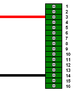
Make sure the battery switch is in the center off position. On the left side of the Super Socket, fasten the red wire from the battery switch under screw terminal 3, and the black wire under terminal 14.
Pass the long hood motor wires through the hole in the components platform nearest the battery. Draw them taught and cut them 4 inches above the platform. Strip enough insulation off the wires to allow them to be fastened under the screw terminals. Flux and tin them. On the left hand side of the Super Socket, fasten the red wire under screw terminal 5, and the black wire under screw terminal 12.
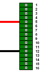
The short hood motor wires should already pass through the hole in the components platform to the right of the Super Socket, and should be the proper length. On the left hand side of the Super Socket, fasten the red wire under screw terminal 5, and the black wire under screw terminal 12.
That completes the installation of the battery switch and motor wires.
REVOLUTION RECEIVER
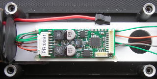
Plug the Revolution receiver into the Super Socket, ensuring all the pins are engaged properly. Plug the remote linking button into the 2 pin header on the back of the receiver. Raise the antenna.
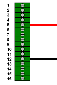
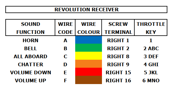
The Revolution receiver has an Auxiliary Control Harness connector with 6 trigger wires, and a black ground wire.
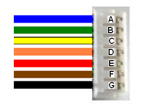
Cut all but the black ground wire to 3 inches in length. Strip enough insulation off the ends of the 6 shortened wires to allow them to be fastened in the screw terminals on the Super Socket, and tin them. Plug the Auxiliary Control Harness connector into the rear of the Revolution receiver.
-
- On the right hand side of the Super Socket fasten:
- the blue wire A for the horn under screw terminal 1,
- the green wire B for the bell under screw terminal 2,
- the yellow wire C for the “All Aboard!” announcement under screw terminal 8,
- the orange wire D for radio chatter under screw terminal 9,
- the red wire E to lower the sound volume under screw terminal 15, and
- the brown trigger wire F to raise the sound volume under screw terminal 16.
Tuck the extra ground wire through hole in the components platform out of the way. That completes the installation of the Revolution receiver.
THE PHOENIX SOUND P8
The Phoenix Sound P8 board will be fastened on styrene strips in between the battery and the hole in the center of the components platform as shown. The strips will allow the power, motor speed, and speaker wires to pass underneath.
From a 1/8 x 1/4 inch styrene strip, cut two pieces 2 1/2 inches long. Cut two more pieces exactly 13/16 of an inch long. Fasten one of the longer pieces on its side to the edge of the platform opposite the battery connector. Using the small pieces as spacers, fasten the other longer piece on edge to the components platform exactly 13/16 of an inch from the first. Remove the spacers.
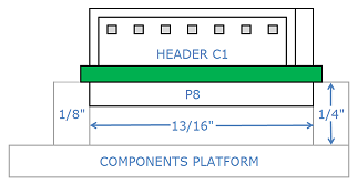
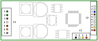
The C1 connector for the P8 has 6 wires: two green, two brown, an orange and a gray. Plug the connector into the header C1 on the end of the P8 board.
Roll the wires near the connector around your finger and place them under the P8. With connector C1 facing the battery, place the sound board on top of the two styrene strips mounted on the components platform. The components on the bottom of the sound board should sit in between the strips, while the P8 circuit board should sit on top of the inside edges. Fasten the corners of the sound board to the strips with small dabs of hot glue.
Cut the 2 green wires to a length that will easily reach the screw terminals on the left side of the Super Socket. Strip enough insulation off the wires to allow them to be fastened under the screw terminals. Tin them, and fasten them under screw terminals 4 and 13. These will provide power to the sound board.
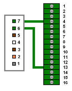
Place the two brown wires with the small white connector through the hole in the center of the components platform and the frame. These will be connected when the speaker is installed in the fuel tank.
Cut the gray and orange wires to a length that will easily reach the screw terminals on the left side of the Super Socket. Strip enough insulation off the wires to allow them to be fastened under the screw terminals. Tin them, and fasten them under screw terminals 7 and 10. These wires will measure the voltage across the motor wires and adjust the sound accordingly.
-
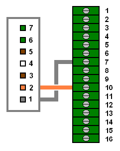
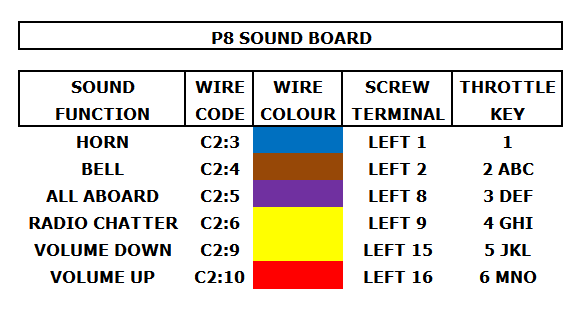
- The C2 connector for the P8 has 9 wires, but in this installation only 6 are used:
- the blue wire (C2:3) for the horn,
- the brown wire (C2:4) for the bell,
- the purple wire (C2:5) for the “All Aboard!” announcement,
- the yellow wire (C2:6) for the radio chatter,
- the yellow wire C2:9) to lower the sound volume, and
- the red wire ((C2:10) to raise the sound volume.
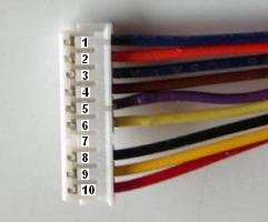
This in the maximum number of sound functions the Revolution Train Engineer can presently trigger. Cut these 6 wires to 3 inches in length. Strip a bit of insulation off the ends of wires and tin them. Plug the connector into the 10-pin header C2 on the P8 board.
-
- On the left side of the Super Socket fasten:
- the blue wire (C2:3) under screw terminal 1,
- the brown wire (C2:3) under screw terminal 2,
- the purple wire (C2:4) under screw terminal 8,
- the yellow wire (C2:5) under screw terminal 9,
- the yellow wire (C2:9) under screw terminal 15, and
- the red wire ((C2:10) under screw terminal 16.
Tuck the extra three wires through hole in the components platform out of the way. That completes the installation of the P8 sound board wires.
THE FUEL TANK
Lay the locomotive on its side on a soft surface. Remove the 2 screws from the bottom of the fuel tank, and place them in a small container.
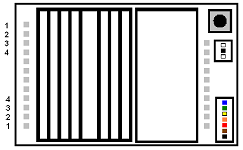
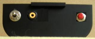
The P8 programming jack will be mounted in the wall of the fuel tank with the battery switch and linking button. This will allow it to be accessible, but hidden when running the locomotive. Place a mark 1 1/4 inches over from the left-hand side of the tank and 1/2 inch down from the top. Drill a hole for the jack using a 5/16 inch bit.
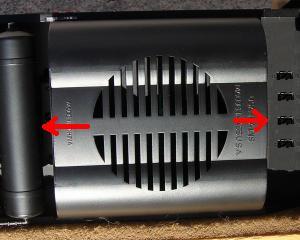
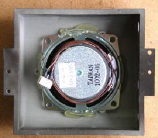
Secure the Phoenix Sound speaker to the bottom of the fuel tank with hot glue, sealing the cracks between the edges of the speaker and the raised portion of the grill.
Put the nut for the programming jack in the Ziploc bag and hot glue the jack to the back of the fuel tank wall.
Plug the connector on the speaker wires into the connector attached to the P8 brown wires C1:3 and C1:5.
Pass the wires for the programming jack through the holes in the center of the frame and the components platform. Fasten the fuel tank back on with the 2 screws in the small container taking care not to pinch any wires.
Plug the programming jack connector into the 4-pin header (C3) on the bottom edge of the P8 sound board.
ASSEMBLING THE LOCOMOTIVE
Remove the 10 screws from the shell and the 4 shorter screws from the battery boxes, and place them in a small container for now. Place the shell on the engine cradle beside the frame.
On the right hand side of the Super Socket, fasten the black ground wire for the headlights labeled HD2 under the screw 6, and the black ground wire for the headlights labeled HD1 under the screw terminal 11.
On the right hand side of the Super Socket, fasten the red wire for the long hood lights under screw terminal 3, and the red wire for the short hood lights under screw terminal 4.
On the right hand side of the Super Socket, fasten the black ground wire for the short hood number board lights under screw terminal 13, and the black ground wire for the long hood number board lights under screw terminal 14.
Check all the wiring for the Super Socket against the following diagram.
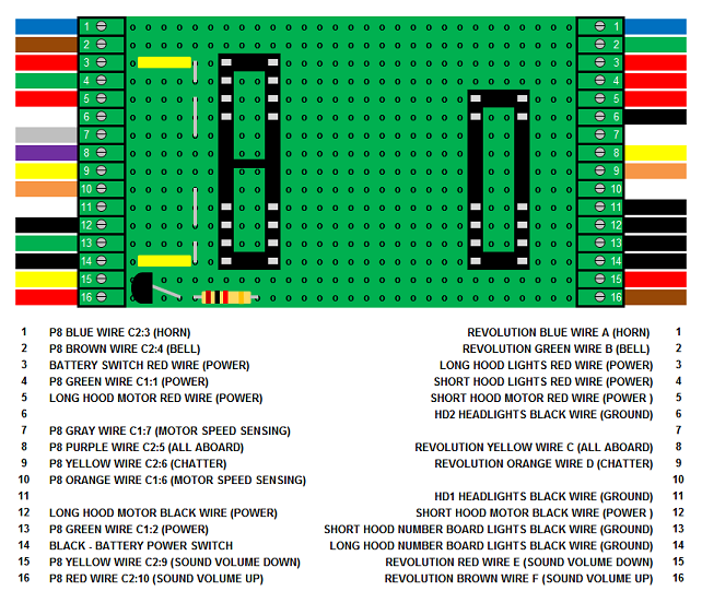
That completes the wiring of the P8 and the Super Socket.
Place the frame on a test stand or rollers so the wheels can turn freely. Turn the Revolution Train Engineer throttle on and select the locomotive. In the Assign Functions menu check to ensure that Function 2 (key aBc2) for the bell is set to “latched”.
Toggle the battery switch down. Test the locomotive and sound board to ensure they respond properly to the throttle. After testing, return the battery switch to its center off position.
Place the shell on the frame ensuring that none of the wires get pinched. Carefully place the locomotive upside down in a soft cradle taking care not to damage the horns. Remove the 2 screws that hold the bottom of the fuel tank to the frame and place them in the small container.
Remove 2 side frames from one side of the locomotive, and place the 6 screws in the small container so they do not get lost. Slip the rear axle of the long hood motor block from its remaining side frame, and flip the motor block towards the center of the locomotive as shown. Fasten 4 of the longest screws back in holes outlined in yellow in the rear motor area.
Flip the long hood motor block back, and slip the axle back in the side frame. Use 3 of the 6 shortest screws in the container to fasten the other side frame back on.
Fasten 4 of the longer screws back in the holes outlined in yellow in the fuel tank area.
Slip the front axle of the short hood motor block from its remaining side frame, and flip the motor block towards the center of the locomotive. Fasten the 2 remaining longest screws back in holes outlined in yellow in the short hood motor block area. Use the last 3 shortest screws in the container to fasten the other side frame back on.
Fasten the 4 screws that hold the battery boxes to the frame back in the holes indicated with the yellow arrows. They can be accessed by turning the truck.
Fasten the fuel tank back on the frame with its 2 screws ensuring that none of the wires get pinched.
Install the handrails to the sides and ends of the locomotive.
CONGRATULATIONS! You have successfully added a Phoenix Sound P8 to a USA Trains GP-9 with on-board: battery power, radio control, and LED lights. ENJOY!