
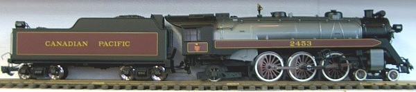
This article details the conversion of an Aristo-Craft Pacific from track power to on-board: battery power, radio control, and sound using a lithium-ion battery and Revolution receiver with steam sounds.
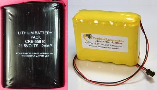
If the smoke unit is not going to be used, an Aristo-Craft lithium-ion battery or Cordless Renovations RCS-1800 would be suitable. If the smoke unit will be used, a Cordless Renovations CR1705 5600mah battery would be more suitable.
The article appears long because it is detailed and includes lots of pictures. But if you take your time and follow it step-by-step it is not difficult, and the results are well worthwhile. Although a Pacific was used for this installation, the instructions could be used as a guide to re-power an Aristo-Craft Mikado as well.
Nothing prevents the locomotive from being restored to its original condition for re-sale at a later date, as anything removed from the locomotive will be stored intact in a small Ziploc bag.
Please read this article carefully, highlighting the components that are needed. Sources of supply are suggested for items not sold by your hobby suppliers. OVGRS members can purchase the required components by contacting Paul Norton.
OPENING THE LOCOMOTIVE
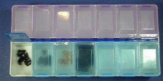
In order to access the Plug and Play printed circuit board to install the Revolution receiver with steam sounds, the locomotive must be opened. To open the locomotive a number different sized screws must be removed. A dollar store pillbox or similar device should be used so they do not get lost or mixed up with each other. If the screws from each part are placed in an adjacent compartment in order of their removal, re-assembling the locomotive correctly will be much easier.
If the front pilot is mounted on the locomotive, it will be much easier to handle the locomotive if it is removed. Remove the two screws from the pilot, and place them in the pillbox. Remove the pilot and set it aside for now.
Carefully pop the front of the handrails out of their two stanchions on either side of the smoke box. Remove the screw on top of the smoke box behind the smoke stack, and place it in the next compartment of the pillbox so it does not get lost.
If the locomotive has the bell mounted on top of the boiler and it can be removed, set the bell and harp aside for now so they do not get damaged. If they cannot be removed, place the locomotive on its side on a soft engine cradle. If an engine cradle is not available, use a slab of soft foam like those used in the packaging of some Bachmann locomotives.
If the bell is mounted on the smoke box above the light, while holding the frame at both ends place the locomotive upside-down on a soft engine cradle.
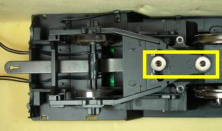
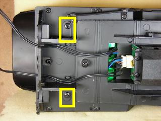
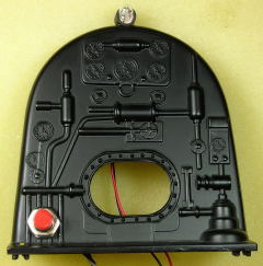
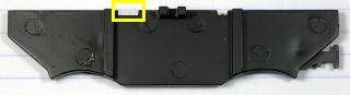
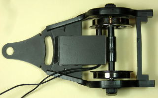
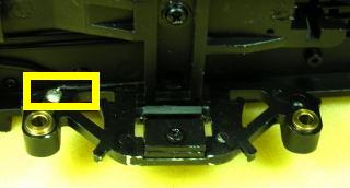
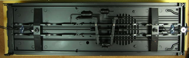
Remove the two screws outlined in yellow that hold the trailing truck and drawbar to the frame. Remove the trailing truck and drawbar taking care not to lose the three washers or spring. Set the trailing truck and drawbar aside for now.
Fasten the spring (55) and washers (56 & 57) to the rear post with the shorter screw (58) with the fine threads.
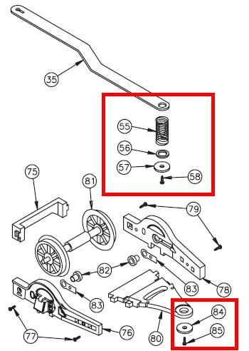
Fasten the washer (84) to the front post with the longer screw (85) with the courser threads.
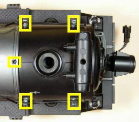
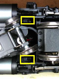
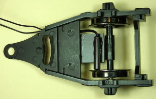
Remove the four screws outlined in yellow that hold the boiler to the frame, and place them in the pillbox compartment with the smoke box screw. There are two under the rear wheels of the pilot truck, and two under the rear drive wheels.
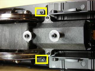
Remove the two screws outlined in yellow that hold the boiler backhead to the frame, and place them in the next compartment of the pillbox.
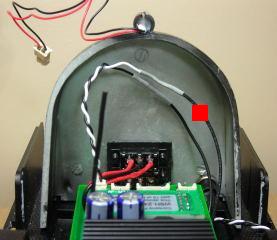
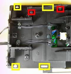
Remove the four screws outlined in yellow that hold the cab to the frame, and place them in the next compartment of the pillbox. The two screws outlined in red will have to be loosened so the piping can be moved back to access the top right cab screw.
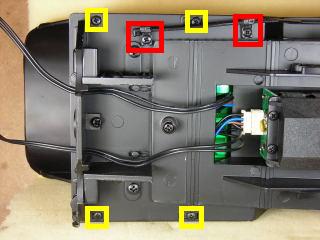
Push up on the cab mounting tabs up just enough to free them from the frame. Push the piping back and snug down the screws outlined in red to hold it in place.
While holding the frame at both ends, set the locomotive on its wheels beside the engine cradle. Carefully lift the cab and boiler from the frame. Set the cab windows that fell out aside for now.
Unplug the cab light from Plug and Play circuit board, and remove the boiler backhead.
Fasten the screws in the pillbox compartments back in the cab, boiler backhead, boiler, and smoke box. Set these items aside for now. Now that the locomotive is opened, the Plug and Play circuit printed board can be accessed.
LOCOMOTIVE WIRING
It is imperative that the track power wiring be removed, so the locomotive can never pick up track power or feed battery power into the tracks. The result could be electronically catastrophic.
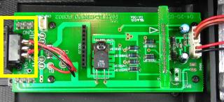
Aristo-Craft Plug and Play locomotives have MU connectors at each end to share track power with other locomotives. As this locomotive will be powered with an on-board battery, the front MU connector is redundant and will be removed. The rear MU connector will remain in place however, as it will be used to transfer battery power from the tender to the receiver.
Carefully unsolder the front MU connector from the front of Plug and Play circuit board. Do not pull on the wires as the traces on the circuit board may lift.
While holding both ends of the frame, set the locomotive on its side on the engine cradle. The MU connector wires pass through the holes in frame under the pilot truck. Pull the wires out from the frame and pilot, and place the MU connector in a Ziploc bag labeled Pacific, as well as, the road name and number of the locomotive.
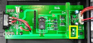
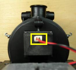
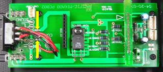
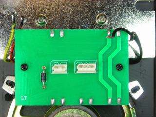
While holding the frame at both ends, set the locomotive on its wheels. This locomotive picks up track power through all six drive wheels. On the back of the Plug and Play circuit board are two slide switches. The top one is the Track/Battery Power Selector Switch.
Testing revealed it was wired in the reverse of the instructions provided in the manual that came with it. Test the locomotive with track power and slide the switch to the battery power position. To prevent the track power from being mistakenly turned on, the track power wiring from the motor block will be removed.
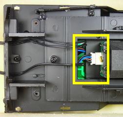
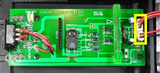
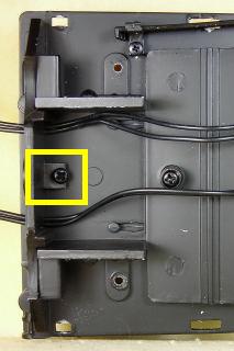
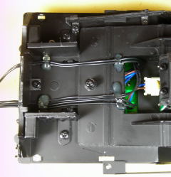
While holding both ends of the frame, set the locomotive on its side on the engine cradle. Unplug the motor block connector outlined in yellow.
While holding the frame at both ends, set the locomotive on its wheels. If the smoke unit is going to be used, skip this paragraph. The smoke unit is mounted on the back of the smoke box. Unplug its connector to ensure it cannot be activated by mistake.
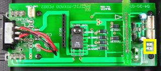
Unplug the voltage regulator and headlight connectors from the circuit board.
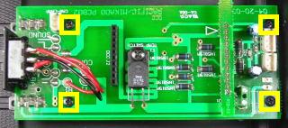
Remove the four screws outlined in yellow from the Plug and Play circuit board, and place them in the pillbox.
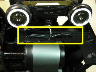
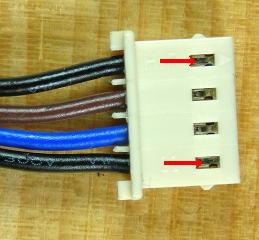
Push the two connectors on the back the locomotive against the rear of the frame to create some slack in the wiring under the Plug and Play circuit board. Lift and turn the board over. The two black wires on the outside of the motor block connector are the track power wires. Push down on the metal terminal tabs and gently pull the two black track power wires out of the connector.
Unsolder the two black track power wires from the Plug and Play circuit board place it in the Ziploc bag.
If the smoke unit is not going to be used, unsolder the red and black wires labeled SMOKE on the circuit board. Place them in the Ziploc bag with the track power wires.
Turn the circuit board back over. Fasten it with the four screws from the pillbox. Plug the voltage regulator and lights connectors back into the front of the circuit board.
While holding both ends of the frame, set the locomotive on its side on the engine cradle. Plug the motor block connector back into the motor block.
While holding both ends of the frame; set the locomotive back on its wheels. That completes the removal of the track power wires from the locomotive.
INSTALLING THE RECEIVER
Remove the two screws from the boiler backhead and place them in the pillbox. Use a 1/8 inch bit in a pin vice to drill a hole in the bottom left hand corner of the backhead in the center of the four pipes and 1/4 inch from the bottom lip. Holding the backhead firmly, slowly and carefully enlarge the hole with a 9/32 inch bit. Mount the remote linking button in the hole. It will be hidden from view when operating, but accessible if need be.
Plug the cab light connector into the 2-pin header labeled CAB-LAMP on the back of the Plug and Play circuit board. Mount the backhead on the floor of the locomotive cab. While holding both ends of the frame, set the locomotive on its side on the engine cradle. Fasten the backhead to the floor with the two screws in the pillbox.
While holding both ends of the frame; set the locomotive back on its wheels.
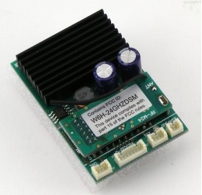
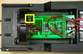
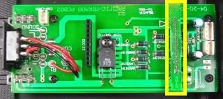
Remove the 12-pin DC circuit board outlined in yellow from the front of the Plug and Play socket.
Install the Revolution receiver, ensuring the pins on both ends are properly lined up with the Plug and Play socket. Straighten the antenna.
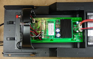
Plug the remote linking button connector into the three-pin header labeled SET on the back of the receiver. Plug the two-wire connector for the black and white speaker wires into the header beside it labeled SPEAKER.
There are currently two connectors on the back of the locomotive. The top connector will transfer battery power from the tender to the receiver. The bottom connector will transfer power from the receiver to the rear light on the tender. An additional connector is now required to transfer power from the receiver to the speaker in the tender.
While holding both ends of the frame, set the locomotive on its side on the engine cradle. Remove the screw outlined in yellow, and place it in the pillbox.
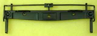
Remove the sill from the rear of the locomotive, and use a file to widen the slot on the left of the sill wide enough to accept an additional two wires. Touch it up with a bit of suitable black paint.
The 2-wire connector sets are available from All Electronics under catalog numbers CON-240. OVGRS members can purchase the connector sets by contacting Paul Norton.
CAUTION: The wires on the connector sets sold by All Electronics may not be positioned the same as the wires on the connectors of lithium-ion batteries and chargers. If not, click on the following link to see how to switch the positions of the AE Connector Set Wiring so that proper polarity is maintained.
With the locking tabs facing up, tape the new connector to the connector for the rear light. Holding the wires taught; re-install the rear sill with the screw in the pillbox.
Pass the wires of the new connector up through the hole in frame. Apply hot glue across the wires to hold them snug against the bottom of the frame. Remove the tape from the connectors.
While holding both ends of the frame; set the locomotive back on its wheels. Trim the black and white speaker connector wires, and the red and black wires of the new connector. Strip 1/4 inch of insulation off the ends of all 4 wires. Solder and shrink wrap the red wire of the new connector to the white wire of the speaker connector, and the black to black.
The chuff sound function can be driven by motor speed (voltage). If that is your preference, you only need to read the paragraph on installing the draw bar and trailing truck in the following paragraphs and then skip to the “Adding the Boiler and Cab” section.
There are a number of places that the reed switch and magnets could be placed. The tender truck wheels are exactly half the size of the locomotive drive wheels. Two magnets on one of them would provide exactly four chuffs for each revolution on the drivers. But that would require another two wires between the locomotive and tender. Four magnets could be glued on the inside of the spokes of a drive wheel, but they would be rather obvious. In this installation two magnets were placed on the back of spokes of one of the trailing truck wheels. While this will not provide exactly four chuffs per revolution of the drivers, they are better hidden and do not require any extra wiring between the locomotive and tender.
Glue a magnet on the back of spoke just inside the rim using a good epoxy. Repeat the process for the spoke 180 degrees from the first. Cut a piece 1 inch by 1 1/2 inches from a piece of 1/16th inch styrene. Spray paint it Krylon Satin Black, and glue it to the top of the trailing truck as close to the axle as possible.
Fasten the reed switch to the bottom of the styrene piece with hot glue so the end of the switch lines up with the rotating magnets.
Remove the screws, washers, and spring for the trailing truck from the bottom of the frame. Fasten the draw bar, spring (55), washer (56), rear of the trailing truck, and washer (57) to the rear post with the shorter screw (58) with the fine threads. Fasten the washer (84) and front of the trailing truck to the front post with the longer screw (85) with the courser threads.
Pass the ends of the wires up through the hole in the frame to the receiver leaving enough slack for the trailing truck to move freely from side to side. While holding both ends of the frame; set the locomotive back on its wheels.
Plug the connector with the white and two black wires and into the header labeled 1-C-2 on the back of the receiver. The white “C” and black “2” wires are used to connect the reed switch. Trim all four wires, and strip 1/4 inch of insulation off the ends. Solder and shrink wrap either one of the reed switch wires to the white “C” wire, and the other to the black “2” wire. It’s the pair of the right of the backhead. Tuck all the wiring into the backhead to keep it out of the way.
ADDING THE BOILER AND CAB.
Remove the screws from the boiler, smoke box, and cab. Place them in two compartments of the pill box. Mount the boiler on the frame ensuring the four tabs on the bottom are properly set in the frame.
Set a window in the cab and lightly tape it in place to the outside of the cab. Repeat the process for the other window. Slide the cab down taking care that none of the wiring in the backhead gets caught. The four tabs on the bottom of the cab should fit snugly in the frame.
Fasten the small screw in the pillbox behind the smoke stack. Carefully pop the front of the handrails back in the two stanchions on either side of the smoke box.
If the bell is mounted on the smoke box above the light, while holding the frame at both ends place the locomotive upside-down on a soft engine cradle. If the locomotive has the bell mounted on top of the boiler and it can be removed, set the bell and harp aside for now so they do not get damaged. If they cannot be removed, place the locomotive on its side on the engine cradle.
Use the four screws in the pillbox to fasten the boiler to the frame. Two go under the rear wheels of the pilot truck, and two under the rear drive wheels.
Using the four screws in the pillbox, fasten the cab to the frame. The two screws outlined in red will have to be loosened so the piping can be moved back to fasten the top right cab screw.
Push the piping back and snug down the screws outlined in red to hold it in place. While holding the frame at both ends, set the locomotive on its wheels.
If the pilot was removed, use the two screws in the pillbox to re-install it. That completes the work on the locomotive.
TENDER WIRING
Like the locomotive, the track power wiring in the tender must be removed. Place the tender upside-down on the work cradle.
The wheels on the front axle of the front truck pass track power to a circuit board in the tender. Slide one wheel from its bushing by gently spreading the sideframe. Slide the other wheel out and set the axle aside for now.
Unsolder the black wire outlined in yellow from each of the axle bushing tabs. Remove the two screws holding the trucks to the frame. Unwind the wires from the loops on top of the front bolster. Insert the front axle back in place. Set the trucks aside, and fasten the two screws back in the frame.
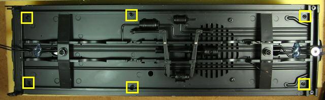
Remove the six screws outlined in yellow that hold the tender body to the frame, and place them in the pillbox.
Carefully turn the tender over and set it on the frame. Lift the body from the frame and set it on the work cradle.
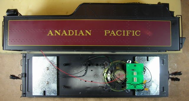
There are red and black wires outlined in yellow on the bottom left hand side of the printed circuit board (PCB) that are used to power the rear light. Unsolder them so the tender body can be removed.
Fasten the six screws in the pillbox back it the tender body, and set it aside for now so it doesn’t get damaged.
There are MU connectors on the right hand side of the PCB that are used to share track power between locomotives. As the locomotive will be powered with an on-board battery in the tender, these connectors and the track power wiring from the front truck are redundant. Unsolder the two MU connectors and the self-resetting polyfuses. Place the MU connectors in the Ziploc bag, and the polyfuses in the pillbox.
There is a connector on the top left hand corner of the PCB that is used to power the rear light which will be replaced by another connector. Unsolder it.
There are two black wires on the bottom of the PCB attached to the speaker. As the speaker will be soldered directly to a new connector, these wires are redundant. Unsolder them. The PCB should now have no wiring attached to it.
There are two metal weight stacks on the frame that cover the unsoldered wires of the three connectors. Remove the two screws from each the weight stack, and place them in the pillbox. Remove the weight stacks and set them aside for now.
Turn the frame over and remove the screw and washer holding the connector wires to the front of the frame.
Remove the hot glue from around the wires at the front and back of the frame. Pull the wires through the holes in the bottom of the frame, and place the three connectors in the Ziploc bag. Re-fasten the automatic stoker cover on the front of the frame with the screw and washer.
That completes the removal of the wiring from the tender.
THE CHARGING CONNECTOR
An All Electronics two-wire connector set will be needed for the charging connector.
The connector sets are available from All Electronics under catalog numbers CON-240. OVGRS members can purchase the connector sets by contacting Paul Norton.
CAUTION: The wires on the connector sets sold by All Electronics may not be positioned the same as the wires on the connectors of lithium-ion batteries and chargers. If not, click on the following link to see how to switch the positions of the AE Connector Set Wiring so that proper polarity is maintained.
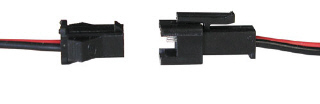
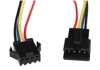
The female half of a connector set shown on the left will be used as the battery charging connector. It has the same connector as an Aristo-Craft lithium-ion battery. It will be mounted on the rear sill of the frame above the coupler.
Remove the two screws from the rear sill of the frame and place them in the next adjacent compartment of the pillbox. Using a small flat screwdriver, pry the rear sill off. Draw a light X from corner to corner in the box in the center of the sill with a pencil. Using an awl or small drill bit in a pin vise, place an indent in the center of the X. Erase the pencil lines. Drill a hole through the sill at the center of the X using a 1/8 inch drill bit in a drill press or pin vise.
Press the rear sill back on the frame and fasten it with the two screws in the pillbox. Using the hole in the sill as a guide, drill a hole through the rear of the frame with the 1/8 inch drill bit in the pin vise.
To make the charging connector inconspicuous, clip the wings off and sand the sides smooth. Polishing the sanded sides on some very fine emery cloth or sandpaper will restore the shine.
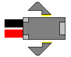
With the locking tab on the charging connector facing up, slip the wires through the hole in the rear sill and the hole in the bottom of the frame. Pull the wires until the charging connector is flush again the sill.
That completes the installation of the charging connector. It will be soldered to the battery switch after the battery and rear weight stack are installed.
THE BATTERY PLATFORM
The lithium-ion battery will be mounted on a styrene platform fastened to the rear weight. To equalize the weight, one of the metal plates will be moved from the rear of the frame to the front weight stack. Place three of the metal plates on the front of the frame, and fasten them with two of the screws from the pillbox.
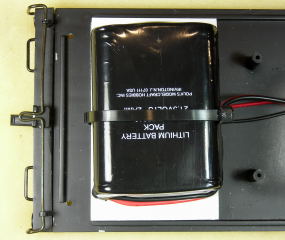
Cut two pieces of styrene the same size as the remaining rear weight plate from a 1/16th of an inch thick sheet of styrene. If the smoke unit and a larger battery will be used, larger pieces of styrene sheet may be required.
Tape the two styrene sheets to the rear weight ensuring all the edges are flush. Using the plate as a guide, drill two holes for the mounting screws through the styrene sheets using a 9/64ths inch bit. Undo the tape and remove the sheets from the weight.
Enlarge the holes in one of the styrene sheets with a 5/16ths inch drill bit. These holes will allow the heads of the screws to be pocketed.
On the other sheet, measure 1 3/4 inches in from the top and bottom edges, and draw two lines across the width. Score and snap the sheet on both lines to divide it into two smaller pieces.
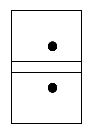
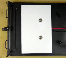
Set the two smaller styrene pieces on top of the metal plate. If the edges are flush and the holes line up, there should be a 1/4 inch channel between the two smaller pieces. Glue larger styrene piece on top of the two smaller styrene pieces. The enlarged holes in it should line around the holes in the smaller styrene pieces and the metal plate, and the edges should be flush with both. When the glue has set, fasten the metal plate and styrene platform on the back of the frame with the two remaining screws in the pillbox.
Cut two strips of double-sided tape 2 1/2 inches long. Place the first strip over the two screws, and the next strip beside it. Fasten the battery on the two strips as shown.
Slip a cable tie through the channel in the platform between the two styrene sheets, and snug it down around the around the battery and it wires.
That completes the installation of the battery. It will be connected after the battery switch is installed.
THE BATTERY SWITCH
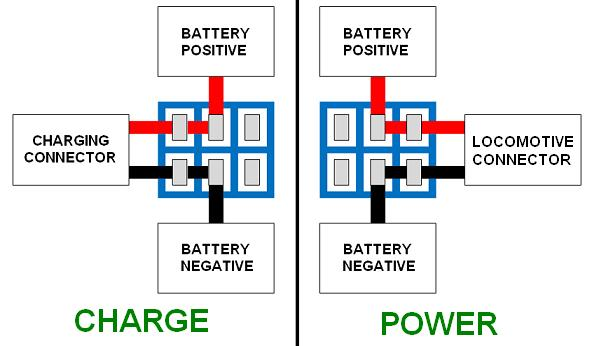
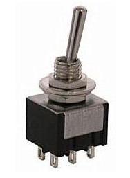
As the battery will be charged on-board, a double-pole double-throw (DPDT) center-off switch is needed to toggle the battery between its charging connector and locomotive battery power connector.
The switch is available from All Electronics under catalog number MTS-12. OVGRS members can purchase the switch by contacting Paul Norton.
As it is easier to solder and shrink wrap the wires to the switch before it is installed, place the switch in a small bench vise with the terminals facing up.
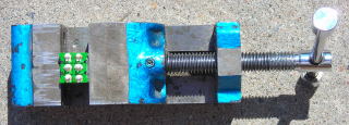
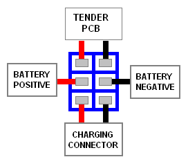
Solder and shrink wrap the wires of the charging connector to the bottom terminals of the switch as shown in the following diagram.
The male connector shown on the right is the same as the one on an Aristo-Craft lithium-ion battery charger. It will be used to connect the battery to the battery switch.
Cut the wires of the connector to 4 inches in length, and strip a bit of insulation off the ends of both. Solder and shrink wrap them to the center terminals of the switch as shown in the following diagram. Do not plug the battery in at this time, as the wiring of the PCB has to be completed.
The battery switch will be connected to PCB with a 5 inch length of red and a 5 inch length of black wire. Solder and shrink wrap the wires to the top terminals of the switch as shown in the diagram above. Check to ensure all the wires on one side of the switch are red, and the other side black.
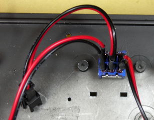
Fasten the battery switch in the 1/4 inch hole on the left side of the frame so it toggles forward and back. The wires for the charging connector should be at the back and wires to the PCB at the front.
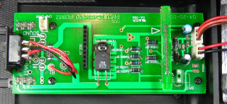
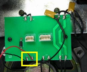
Solder a shrink wrap the open end of the black wire to a lead on a polyfuse from the pillbox. Solder the other lead of the polyfuse to the inside solder pad on the bottom right hand corner of the PCB as shown in the following picture.
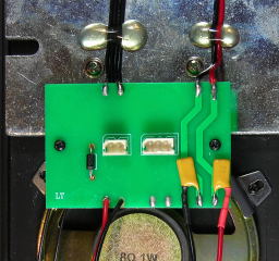
Solder a shrink wrap the open end of the red wire to a lead on a polyfuse from the pillbox. Solder the other lead of the polyfuse to the outside solder pad on the bottom right hand corner of the PCB as shown.
The female half of a connector set shown on the left will be used as the connector to provide battery power from the tender to the receiver in the locomotive. It has the same connector as an Aristo-Craft lithium-ion battery.
Cut the wires of the connector to 4 inches in length. With the locking tab on the connector facing up, solder and shrink wrap the black wire to the inside solder pad on the top right hand corner of the PCB as shown in the following picture.
Solder and shrink wrap the red wire to the outside solder pad on the top right hand corner of the PCB as shown.
That completes the installation of the battery switch and its wiring. The battery will be plugged in once the rest of the wiring for the PBC is installed.
REAR LIGHT AND SPEAKER
The male half of a connector set shown on the right will be used as a connector to provide power to the rear light from the receiver. It has the same connector as an Aristo-Craft lithium-ion battery.
Cut the wires of the connector to 4 inches in length. Solder and shrink wrap the black wire to the inside solder pad on the top left hand corner of the PCB, and the red to the outside as shown in the following picture.

The rear light wires attached to the tender shell can be soldered to the solder pads on the bottom left hand corner of the PCB: the black wire to the inside solder pad and the red to the outside. But to allow the tender body to be removed and set aside a connector set must be used. Cut all four wires of the connector set to 2 inches in length, and strip a small piece of insulation off them all. Solder one of the black wires at one end of the connector set to the inside solder pad, and the red to the outside. Solder and shrink wrap the black wire at the other end of the connector set to the black wire of the rear light, and the red to red.
The male half of a connector set shown on the right will be used as a connector to provide power to the speaker from the receiver. It has the same connector as an Aristo-Craft lithium-ion battery.
Pass the wires of the connector under the PCB and inside the wires for the rear light. Tape the connector to the connector for the rear light. Fasten the wires of all the connectors to the front weight stack with a couple of good runs of hot glue near the screws. This will provide stress relief should the locomotive and tender accidently uncouple while operating, but allow enough flexibility to tuck the connectors under the step of the tender out of sight while operating.
Remove the tape from the rear light and speaker connectors. Run the speaker wires around the speaker to the terminals. Solder the red wire to the positive terminal, and the black to the negative.
OPTIONAL: There is the possibility that the rear light and speaker connectors on the locomotive and tender could be mistakenly cross-connected. To eliminate that possibility, the shells from a 4-wire connector set could be substituted for the shells of the rear light and speaker 2-wire connector sets.
The wires from the 4-wire connector shells can be removed the same way all the two-wire AE Connector Set Wiring was changed. The wires from both the locomotive and tender 2-wire connectors should be removed one at a time and placed in the new connectors, in order to maintain the proper order of the rear light and speaker wiring.
The connector sets are available from All Electronics under catalog numbers CON-440. OVGRS members can purchase the connector sets by contacting Paul Norton.
That completes the installation of the rear light and speaker connectors on the tender.
TESTING THE WIRING
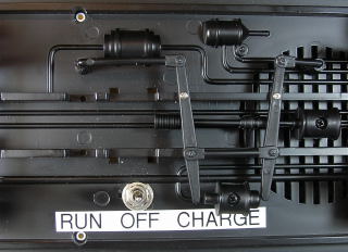
Turn the frame over and place it on the engine cradle. Add a “RUN” label behind the battery switch and a “CHARGE” label in front of it.
Remove the two screws for the trucks from the frame. Re-install the trucks. Make sure the battery switch is in the center-off position. Turn the frame over. Before plugging in the battery, check to ensure the colours of the wires on the battery connector and the connector soldered to center terminals of the switch are a colour match. Plug the connectors together.
Plug the male half of a connector set to into the charging connector on the rear of the frame. Toggle the switch to the front, and use a voltage meter across the free end of the wires to ensure the polarity is correct.
Plug the male half of the connector set to into the MU connector on the front of the frame. Toggle the switch rearward, and use a voltage meter across the free end of the wires to ensure the polarity is correct. Return the switch to its center-off position.
That completes the installation of the testing of the battery charging connector and battery power connector.
CHARGING THE BATTERY
If the battery has not been charged, use an Aristo-Craft, lithium-ion battery charger to top it up. If you have the old style charger without the full charge indicator, test the battery once an hour. A fully charged Aristo-Craft lithium-ion battery should read no more 25.2 volts, and should not require any more than 4 hours on the charger.
PROGRAMMING AND TESTING THE RECEIVER
Make sure the battery switch is in its center-off position. Remove the 6 screws from the tender body and place them in the pillbox. If installed, plug the rear light connectors in the tender together. Set the shell on the frame taking care not to pinch any wiring.
To program the receiver follow the instructions in the Installation and Operation Manual for the Revolution Train Engineer on the CD that came with the set. The Revised Manual and other information is also available on the Aristo-Craft web site as an Adobe pdf file. To read or download the revised manual, click on the link.
Carefully place the locomotive on a test stand or rollers so the wheels can turn freely. Plug in all the connectors between the locomotive and tender, taking care to ensure the rear light and speaker connectors are not incorrectly plugged into to each other. Toggle the battery switch to the run position, and program the receiver.
Test to ensure the motors, sound, and lights respond properly to the throttle, and that the lights and motor direction are in synch. After testing, return the battery switch to its center off position.
Unplug the connectors between the locomotive and tender. Carefully turn tender over and place it on the engine cradle. Fasten the tender body to the frame using the 6 screws in the pillbox. Set the tender on its wheels.
CONGRATULATIONS! You have successfully converted an Aristo-Craft Pacific to on-board, battery power and radio control with steam sounds.
ENJOY!
2 comments
I just got an older Aristo Craft Pacific and I don’t understand where to put the smoke fluid into the locomotive. It came with no instructions, of course! Can you show me a diagram of where to put it please? Thank you.
Hi Rick!
Under the smoke box is a smoke fluid reservoir that looks like a trunk. Pop the lid off that and add 25 drops of smoke fluid in it. Push the slide switch beside the reservoir towards the locomotive to power the smoke unit.
When the smoke stops, draw the slide back to stop the power to the smoke unit or it will burn out.